|
This Photo Gallery contains examples of
EEE Parts and related hardware that have grown metal whiskers. This
photo gallery is by no means a complete archive of the types of parts that
have been known to whisker, but instead contains only those part types for
which NASA GSFC has been able to obtain permission to share photographic evidence.
The growth of whiskers
is NOT unique to a specific part type but rather is related to the materials
and processes used to plate the components as well as the subsequent
environment/handling conditions to which the parts are exposed. As such, users are urged
to exercise caution when selecting components that are plated with
materials and processes that are prone to whisker formation.
Photo of
the Month Archive
|
EEE Parts
|
Mechanical Hardware and Structures
|
- Capacitors
Circuit Breakers
Connectors
Crystals
|
- Discrete Semiconductors
Electromagnetic Relays
Hybrids and Microcircuits
Resistors
Transformers
Wave Guides
|
- Bus Bars and Rails
Cable Trays
Card Guides
Floor Tiles, Raised Computer Room
Hardware
Pipe/Conduit
Terminal Lugs
 | Terminal Lugs, Ring Type,
Tin-Plated |
| Terminal Lugs, Spade Type,
Tin-Plated |
| Terminal Lugs, Ring Type,
Tin-Plated, Mfr "A" |
| Terminal Lugs, Ring Type,
Tin-Plated, Mfr "B"
|
Test Points
|

Capacitors
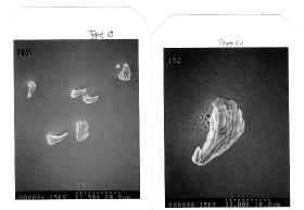
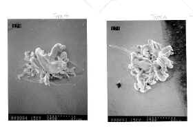
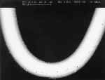
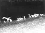
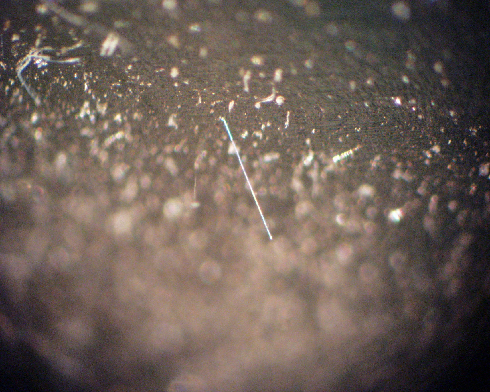
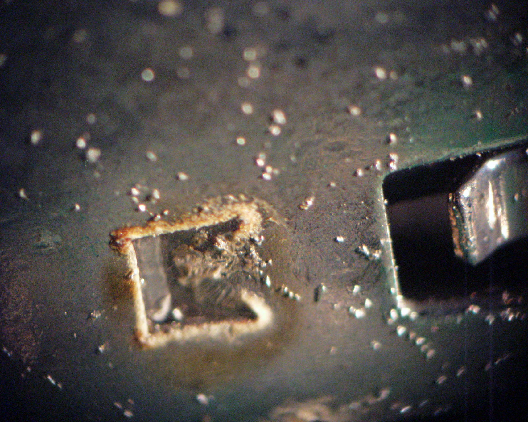
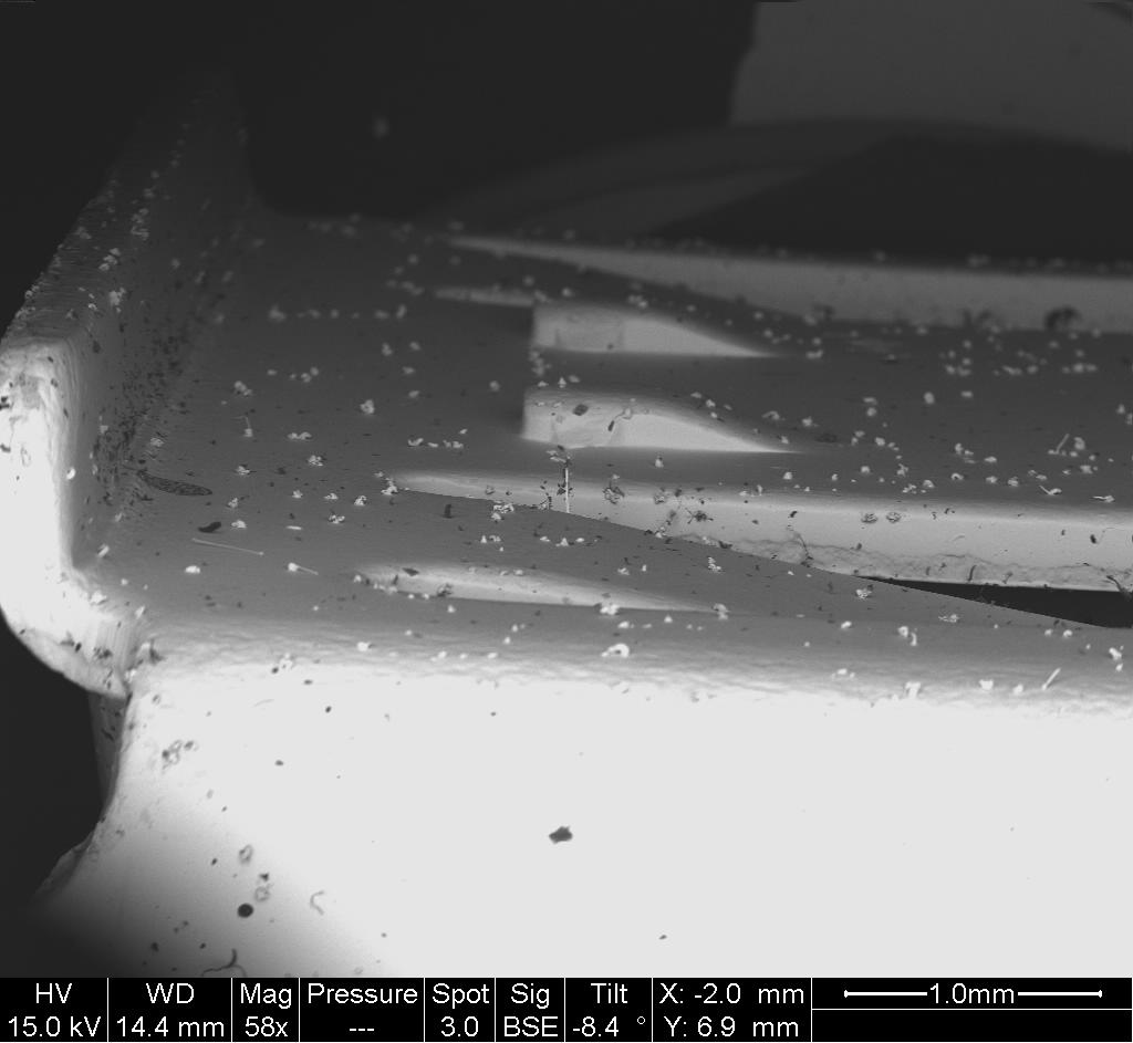
Capacitor, Multilayer Ceramic Chip
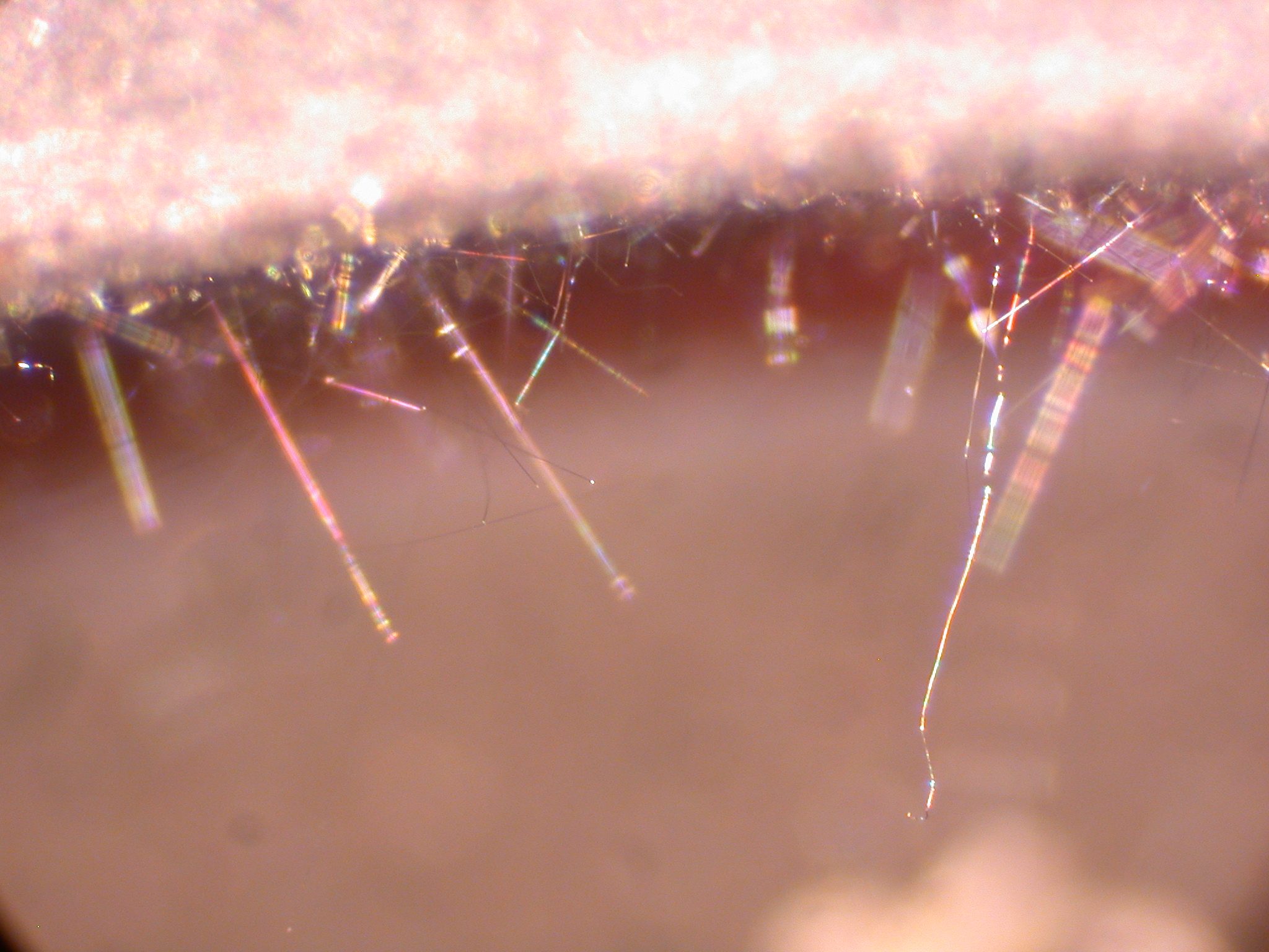
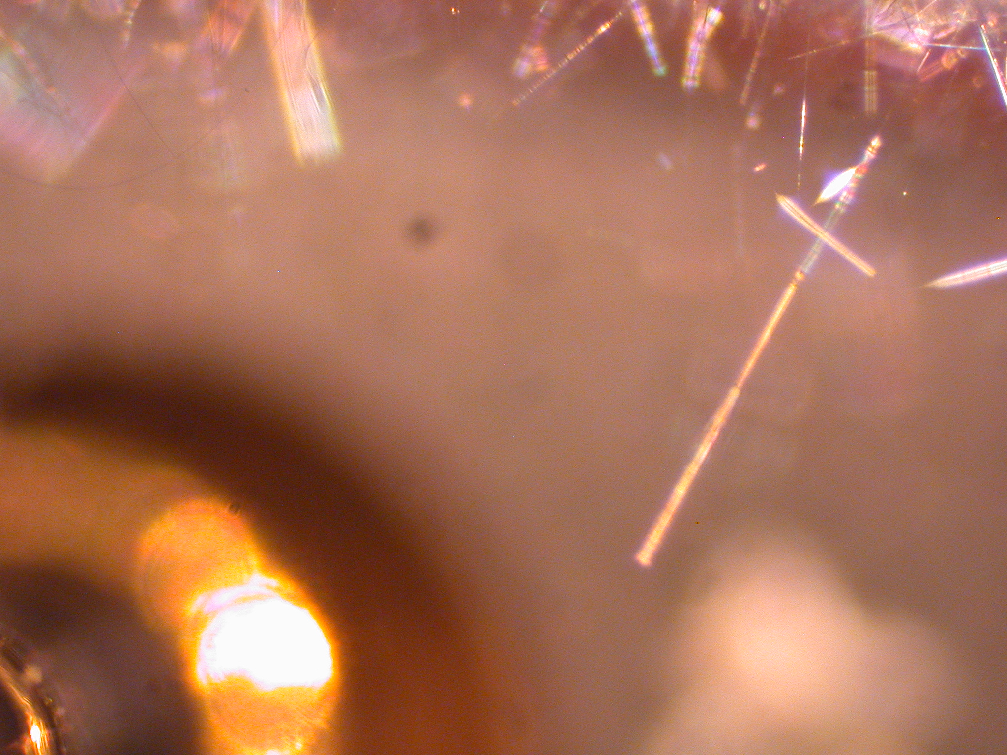
These commercial
(size 0805) ceramic chip capacitors have pure tin plated
terminations over a nickel barrier layer. The user mounted them using conductive epoxy (i.e, not
reflow soldered) and after thermal cycle testing discovered the tin
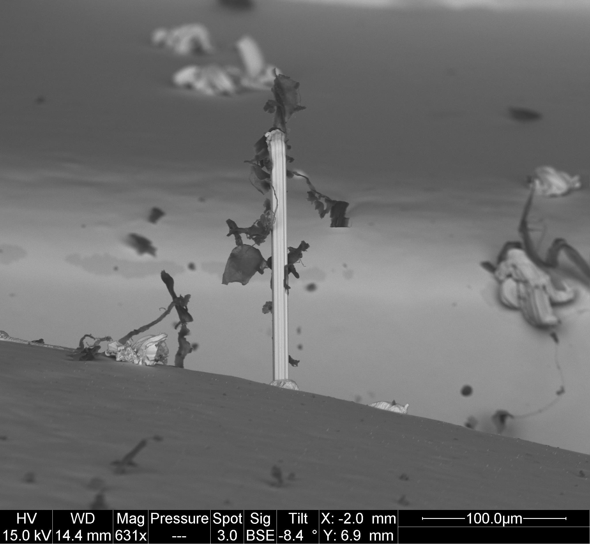
whisker farm. After thermal cycling max. whisker lengths of 100
microns were observed. HOWEVER, after additional room ambient
storage (6 - 8 months) the whiskers continued to grow with some in excess
of 200 microns (max. length ~240 microns). It has NOT been experimentally shown whether soldering these parts to the board
would have eliminated the whisker concern through either reflow of the
terminations or mixing of "most" of the termination surface with
the mounting solder (typically tin/lead based). See NASA
GSFC Experiment #5 for more info.
|
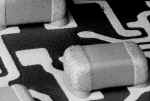
Epoxy Mounted Cap:
whiskers on terminations
|
Top Side of Termination
Tin whiskers on terminations
|
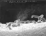
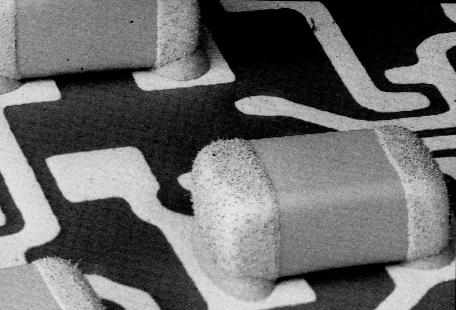
Close Up:
Tin whiskers on terminations
|
Close Up:
Tin whiskers on terminations
|
|

Tin Whiskers continued to grow during room ambient storage after
completion of t-cycle
|

Various odd-shaped Tin whisker extrusions
|
>150um long Tin whisker
|
More Tin whiskers
|
|
Close Up:
Tin whiskers on termination
|
190um long Tin whisker
|
|
|
Photos
Courtesy of I. Hernefjord & NASA Goddard
Capacitor, Variable Air Spaced
In 1946 Howard Cobb of the Aircraft Radio Corporation
(ARC) published an article "Cadmium Whiskers" that many consider
to be the first public reference describing how metal whisker growth
affected the proper functioning of electronic systems. In his
article he describes how cadmium whisker formation on the cadmium-coated
plates of variable air-spaced capacitors were producing plate to plate
short circuits in radio equipment used during World War II. The news
that cadmium coatings could produce damaging whiskers reached others such
as Bell Laboratories (less than 20 miles from ARC) who switched from
cadmium to tin and zinc coatings only later to discover that these metals
also sometimes produce damaging metal whiskers.
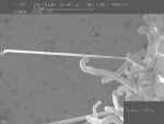
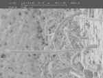
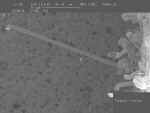
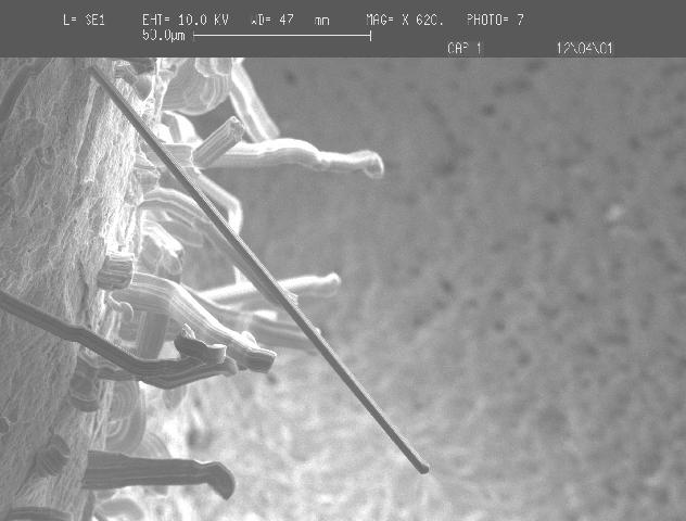
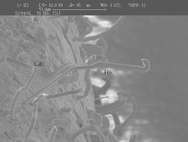
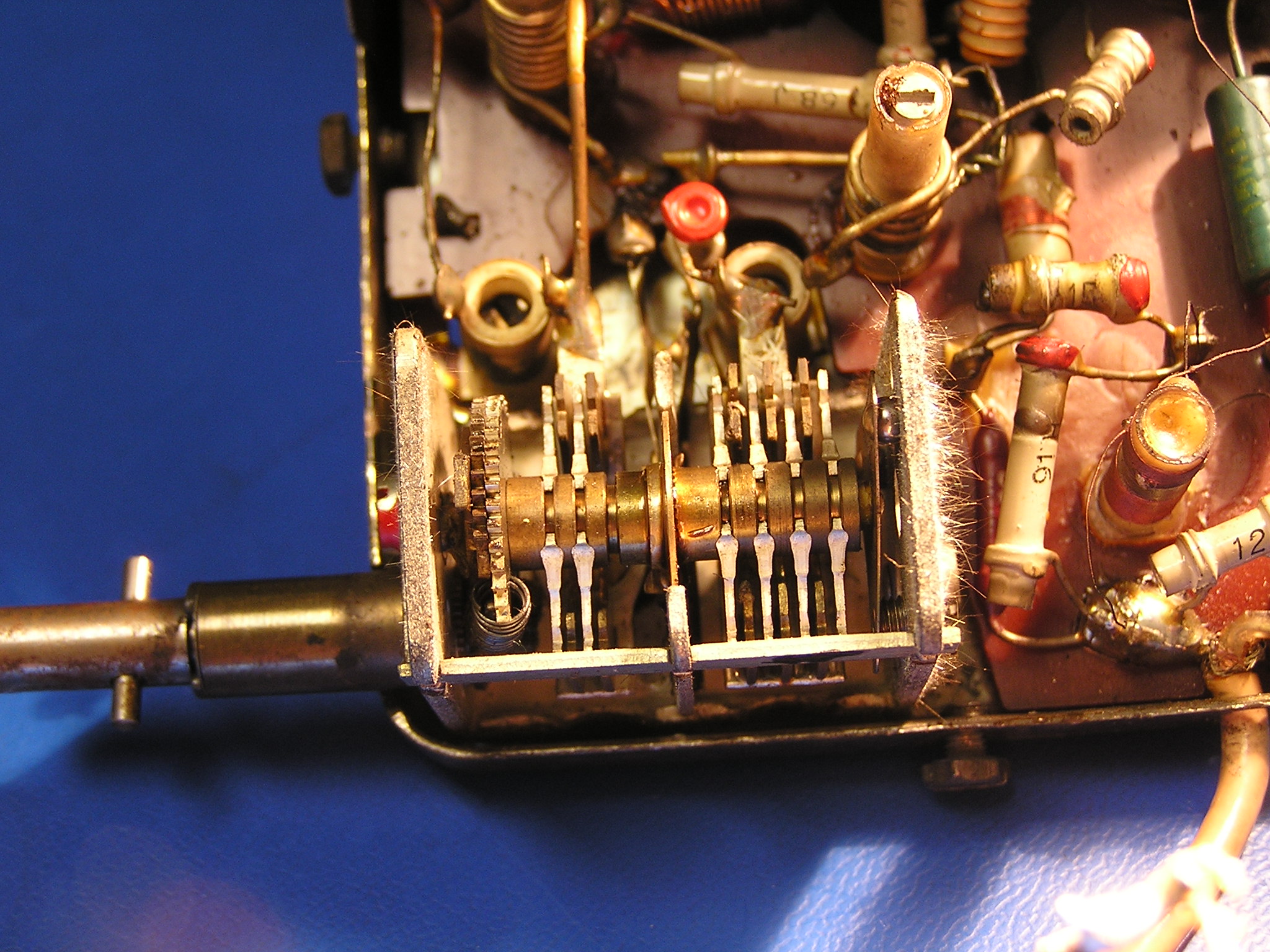
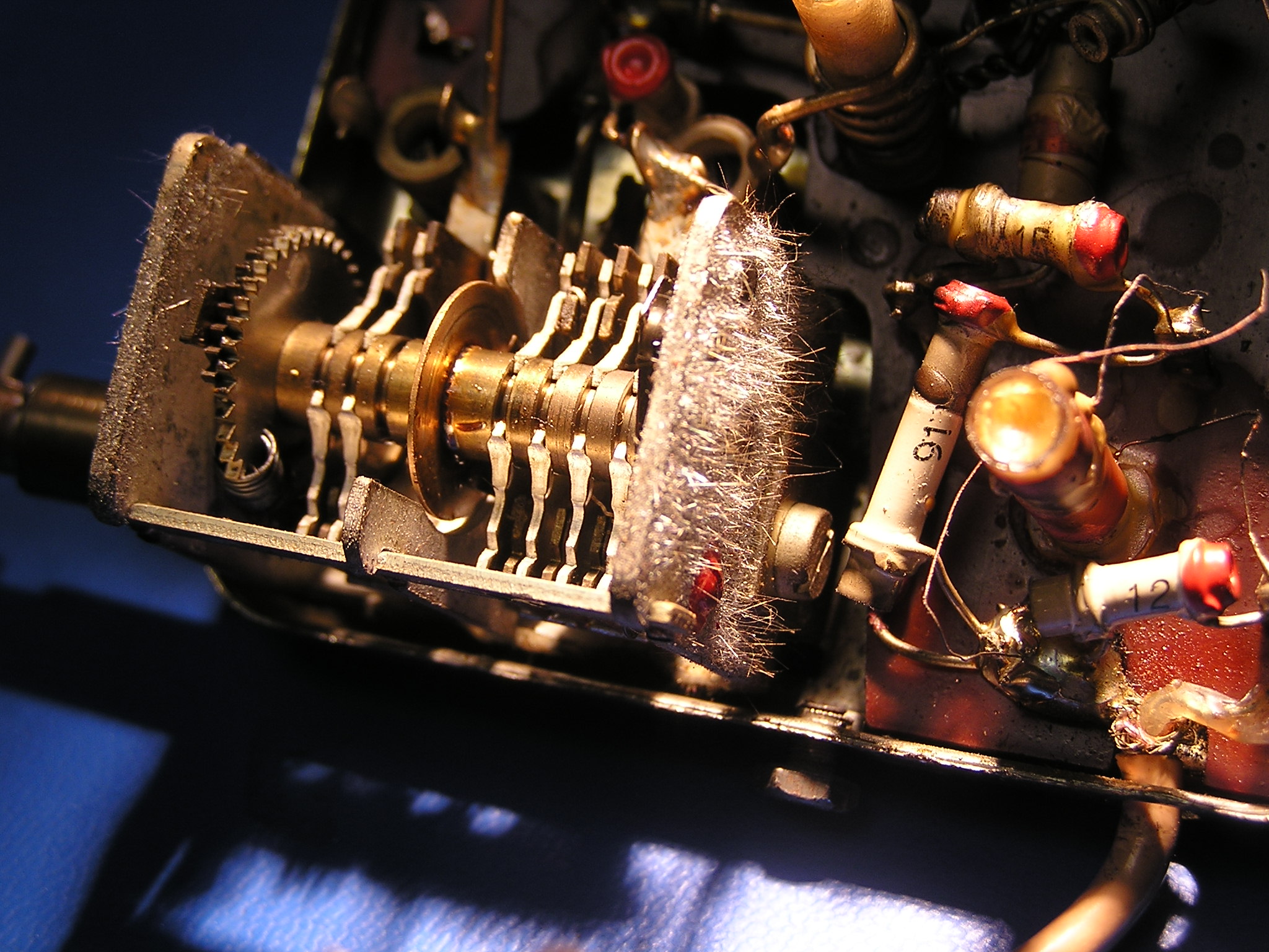
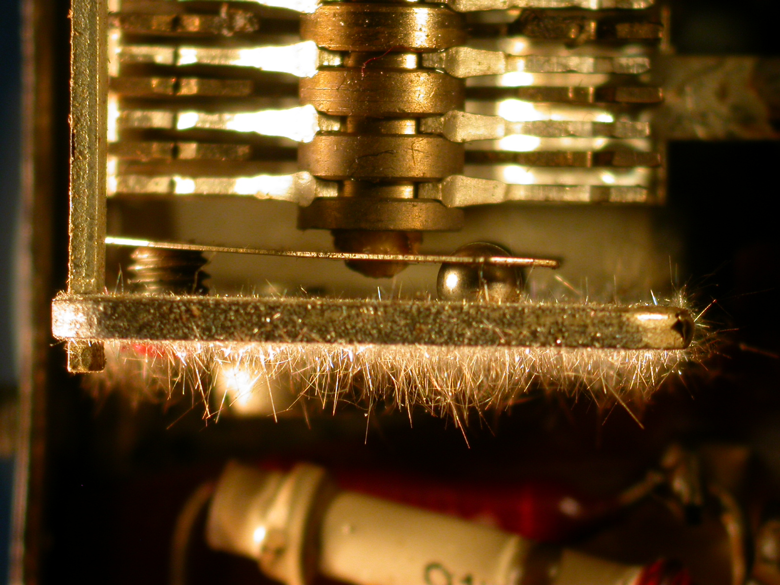
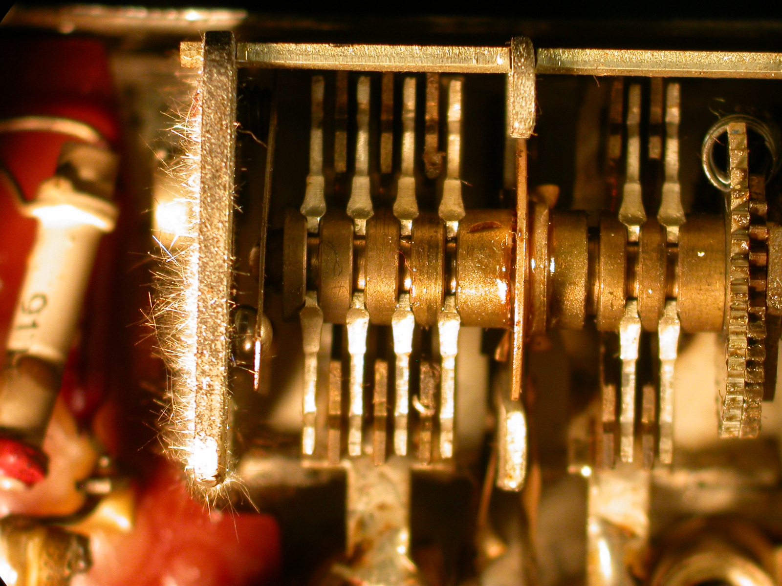
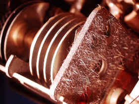
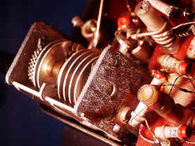
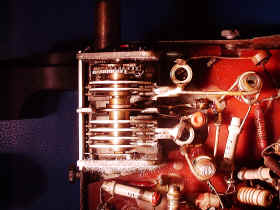
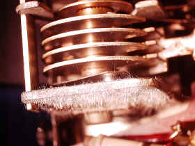
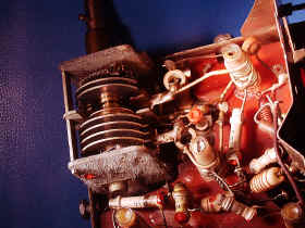
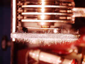
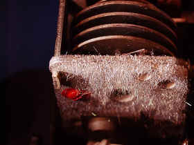
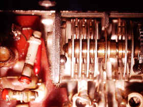
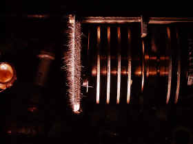
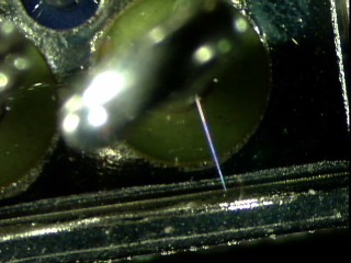
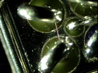
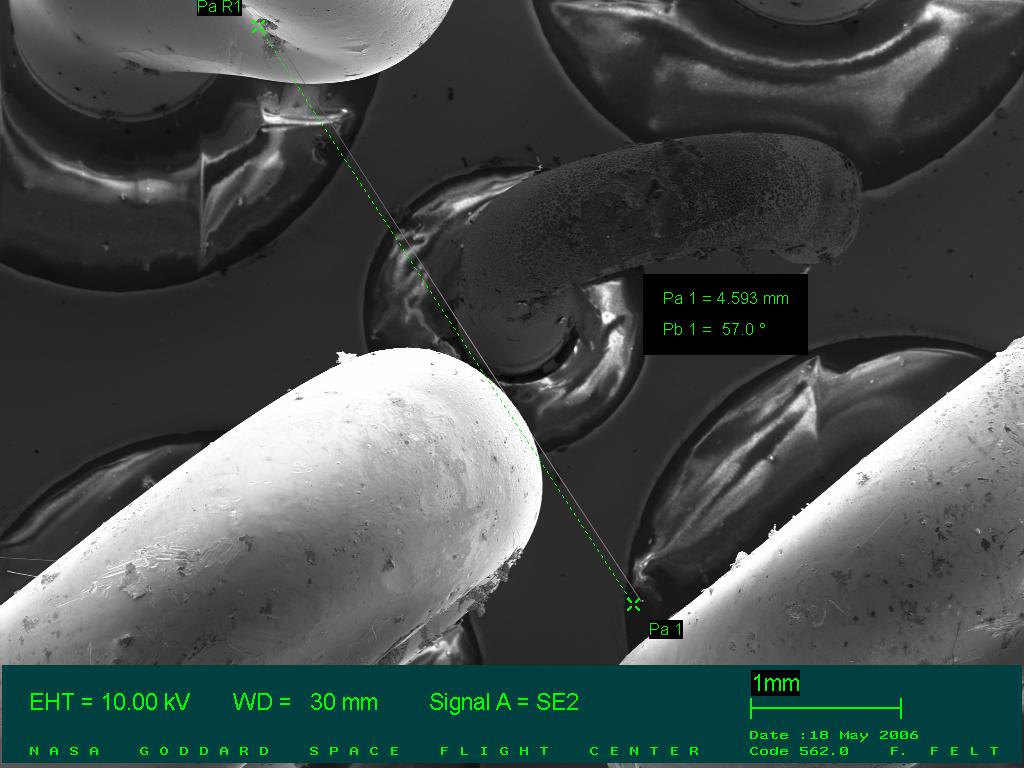
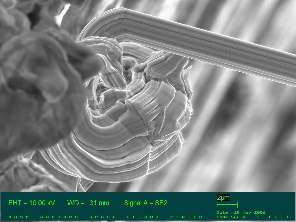
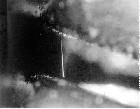
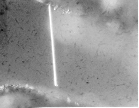
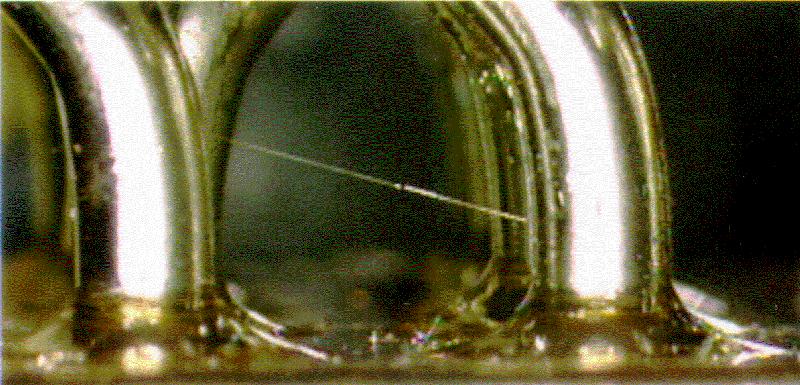
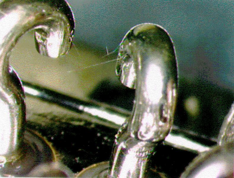
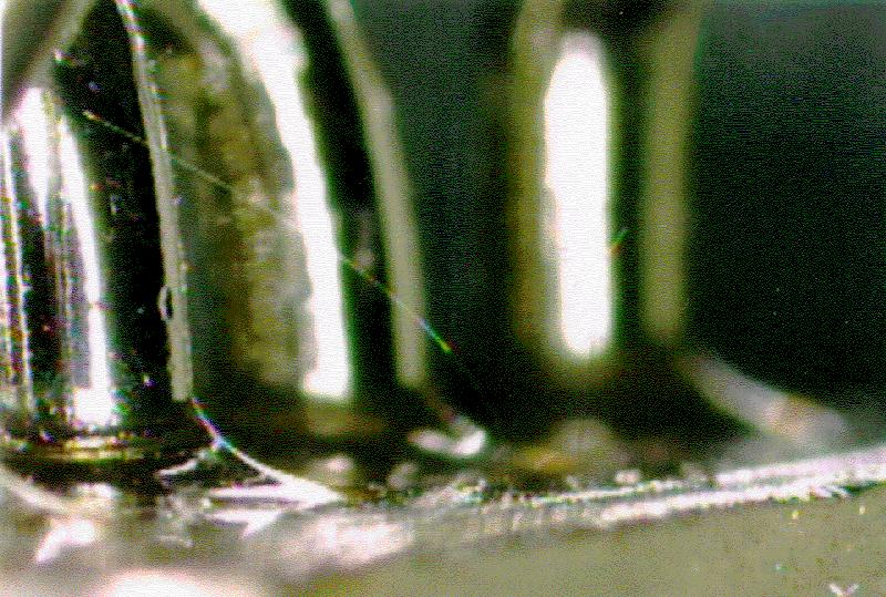
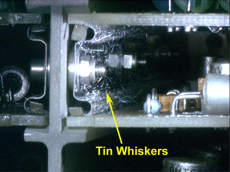
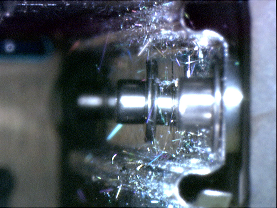
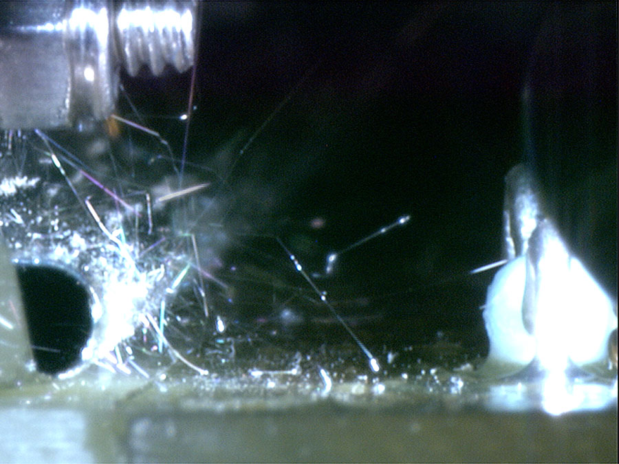
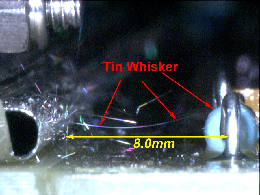
The specimen shown below is a 1960s era variable
air-spaced capacitor (similar to the one described by Cobb) that uses a
tin-plated frame. The extensive tin whisker formation on this capacitor
extend in excess of 8-millimeters in some cases. NASA Goddard greatly
appreciates Frank Nikolajsen, a vintage radio collector in Denmark, for
contacting us and then donating this treasure piece for analysis and
historical preservation.
See
a video of this air capacitor demonstrating their extreme lengths and
flexibility in normal air flow
Images courtesy of NASA-GSFC
Circuit
Breakers
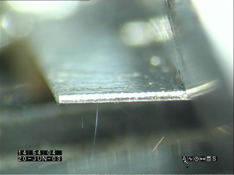
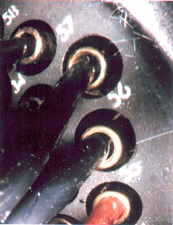
Circuit Breaker Contacts
The
images below depict tin whiskers growing on the "bright"
tin-plated copper contacts inside of a circuit breaker.
Read
More About the Field Failures Experienced as a Result of the Tin Whiskers
on These Circuit Breakers
Source: Anonymous
Connectors
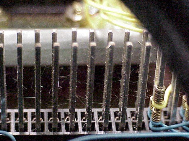
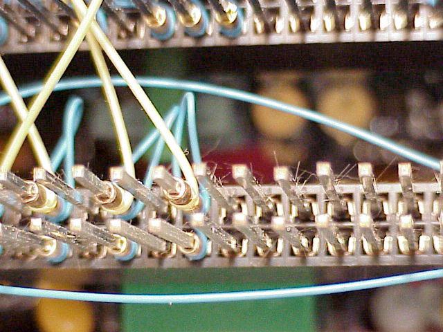
Wire Wrap Terminals
Tin-plated wire wrap terminals below grew a very high
density (#/area) of tin whiskers having sufficient length to bridge
adjacent terminals.
Read more about this experience in the following GE
Power Management Service Bulletin
Images courtesy of GE Industrial
ZIFF Socket
ZIFF Socket below has tin whiskers growing from tin-plated
surfaces immediately adjacent to areas where the pin presses against the
contact.
Metal whisker growth has frequently been observed in applications where
surfaces are subjected to externally applied pressure.
Source - anonymous (circa 2006)
ZIFF Socket with Tin Plated Surfaces |
Tin Whisker on ZIFF Socket |
Tin Whisker on ZIFF Socket |
Tin Whisker on ZIFF Socket |
Source: Anonymous
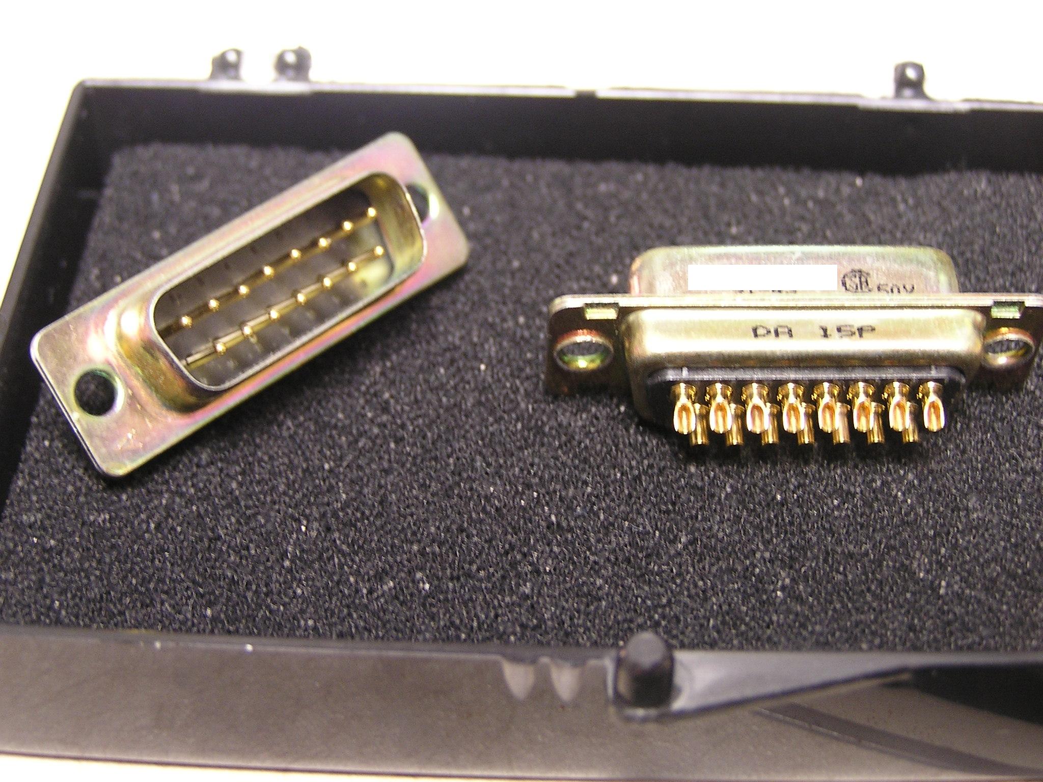
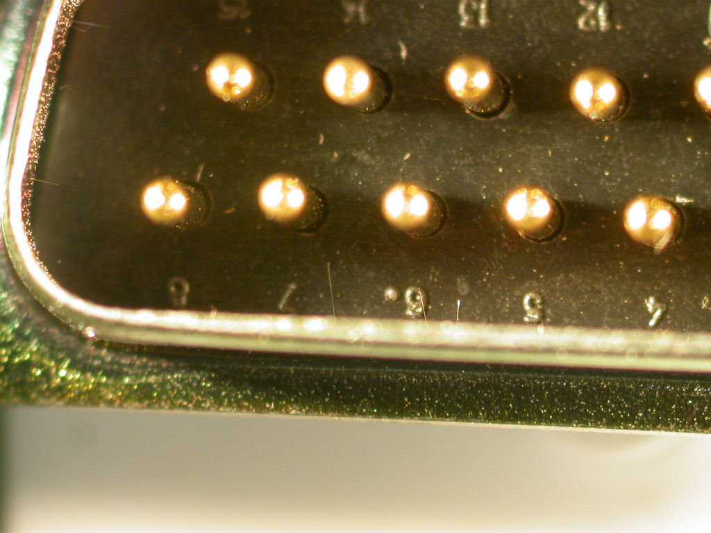
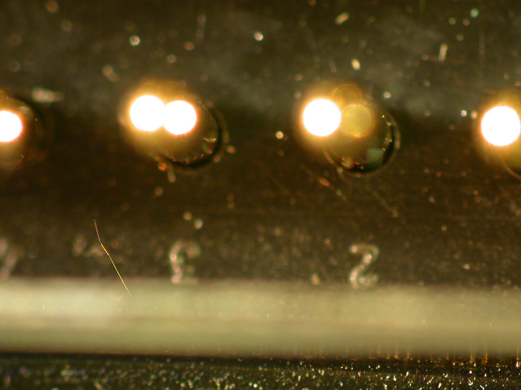
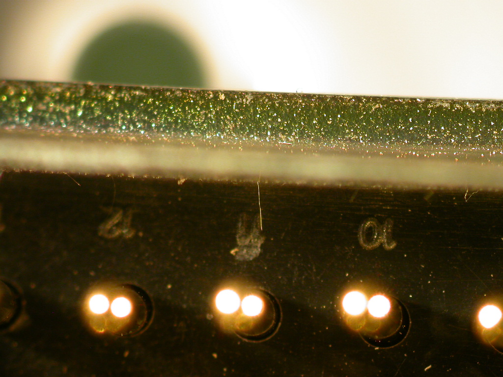
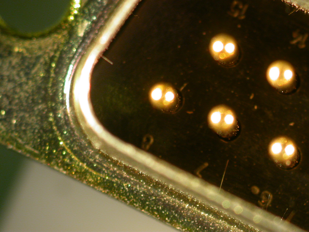
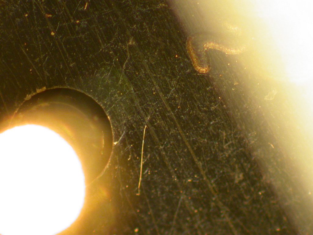
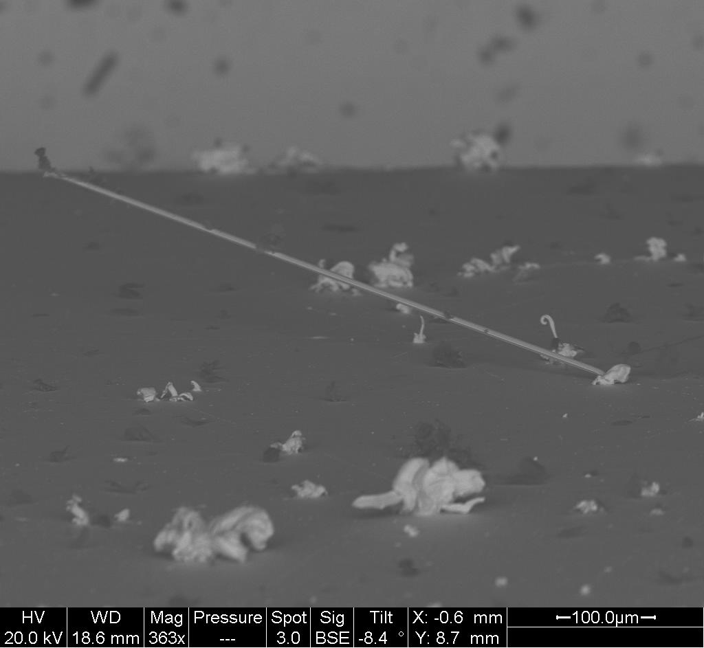
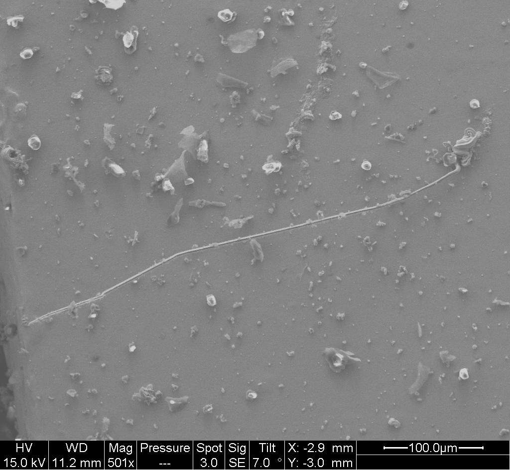
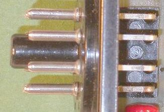
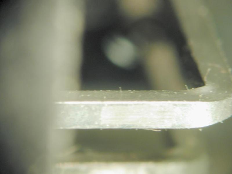
Connector, D-Sub, Tin-Plated Shell
Connector shells are often plated with tin, zinc or
cadmium finishes for corrosion protection.
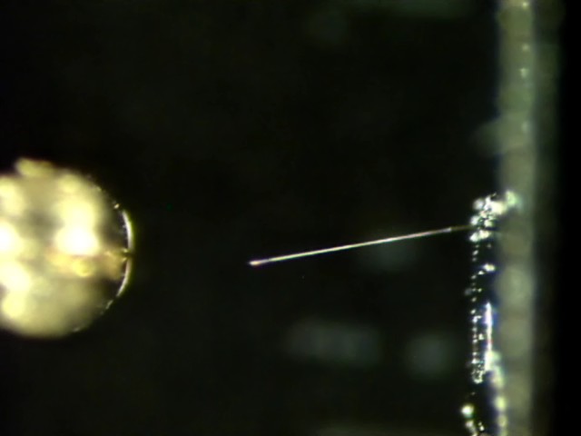
The examples below show tin whiskers and zinc whiskers growing from
D-subminiature connector shells including an example of a whisker bridging
from the connector shell to a gold-plated connector pin
|
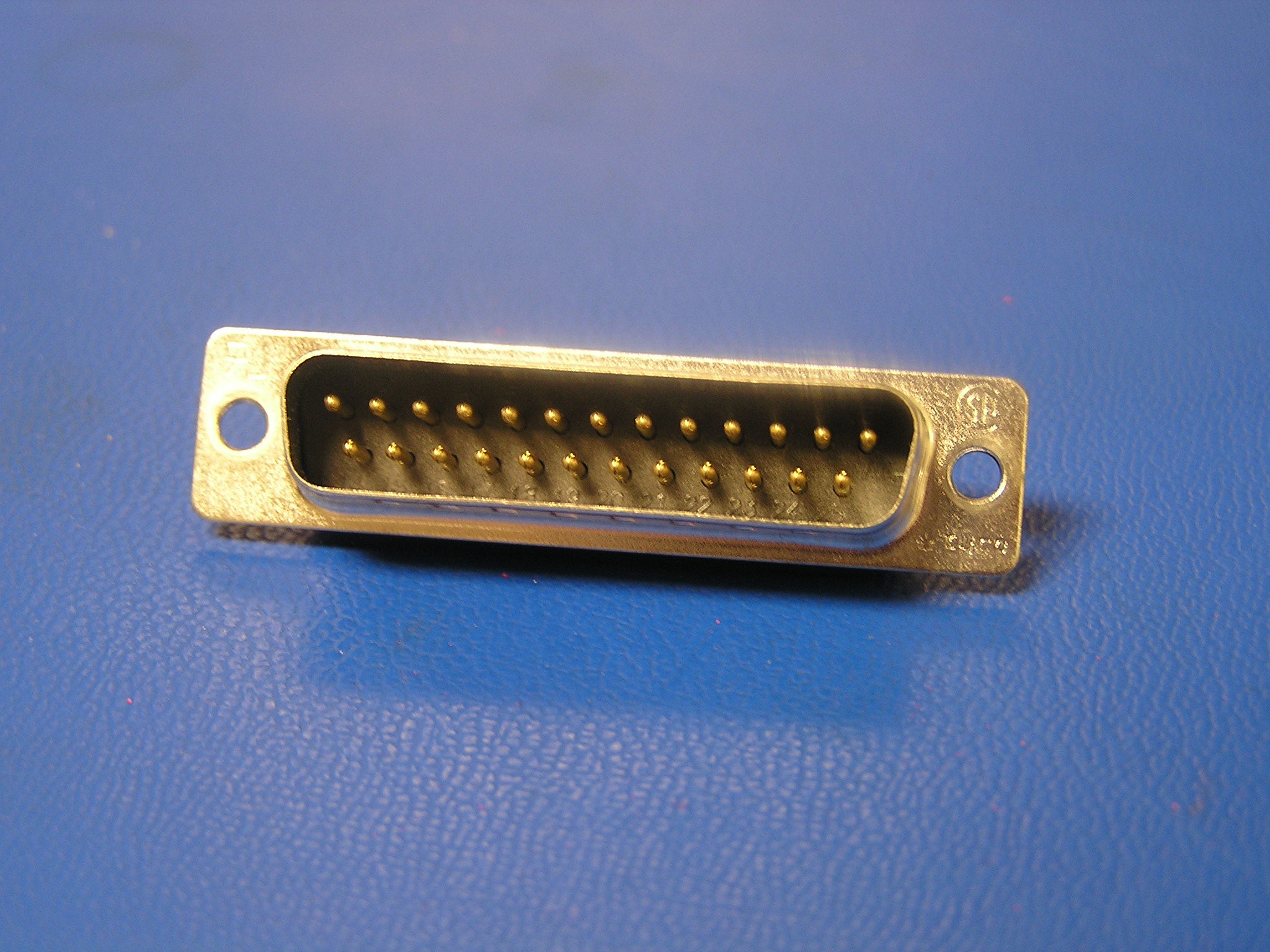
Tin-plated D-Sub Connector Shell
|
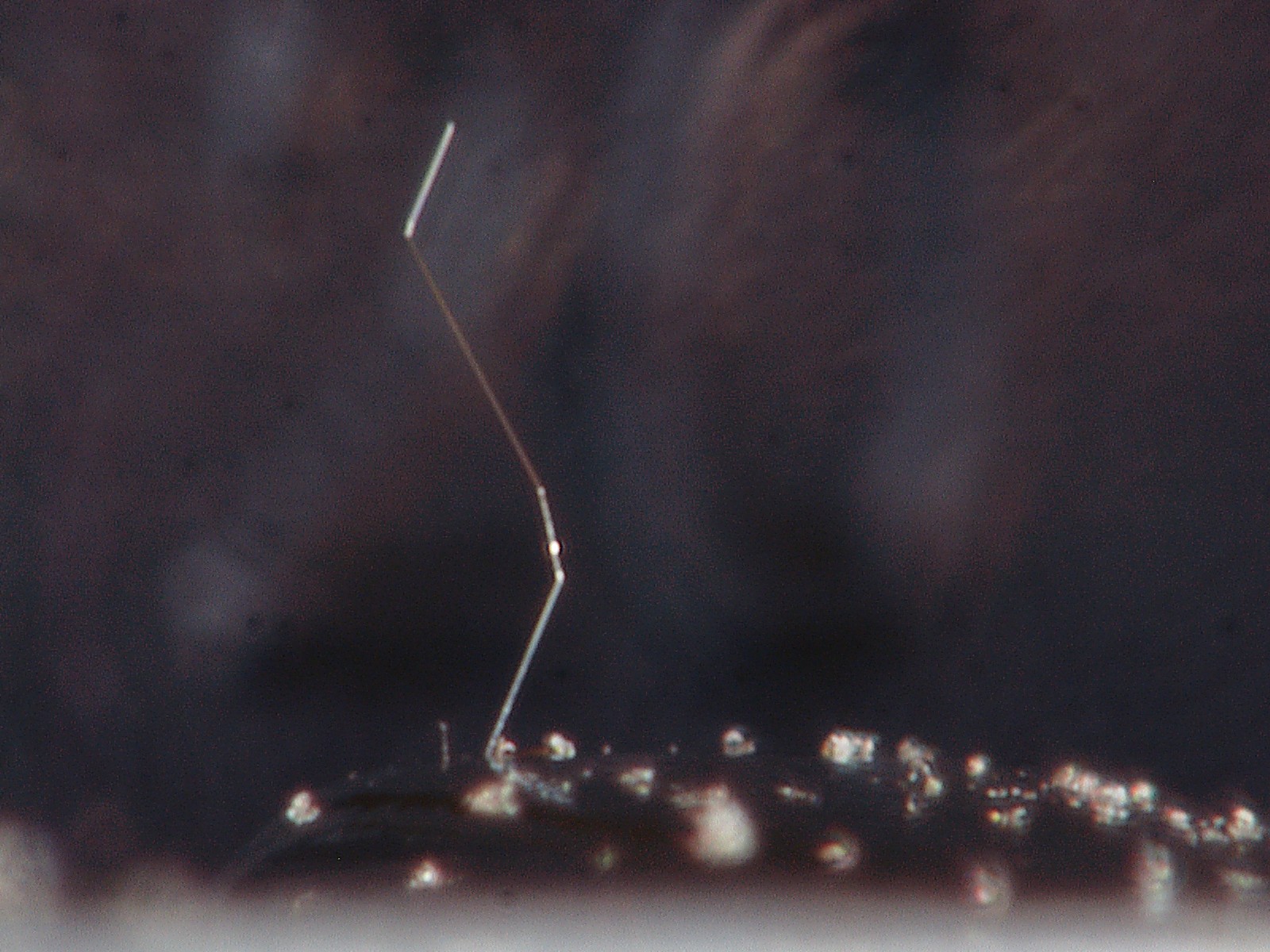
Tin whisker growing from connector shell
|
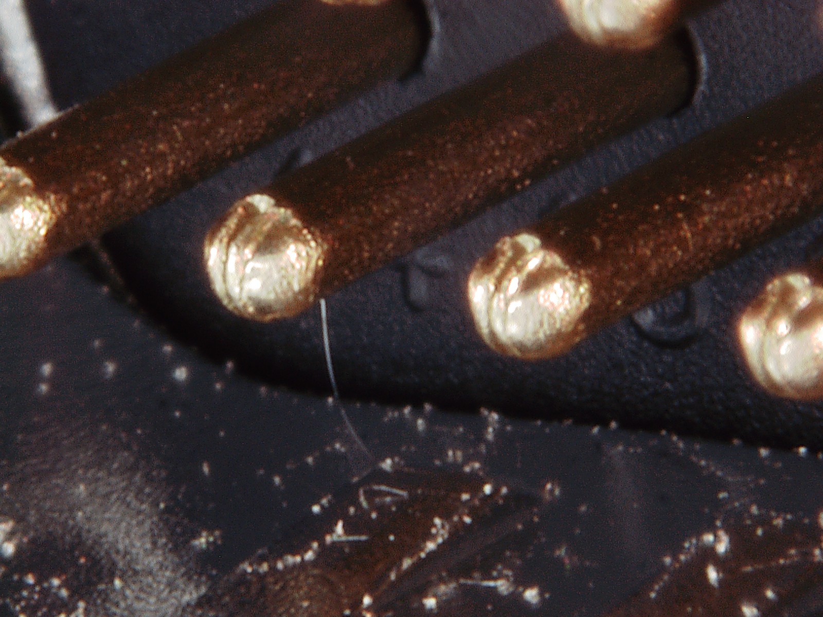
Tin whisker shorting connector shell to pin
|
|
Tin Whiskers on DSub Connector Shell
Photo taken in 2006
|
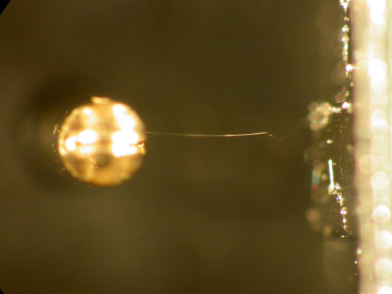
Tin Whisker on DSub Connector Shell
Shorting to Connector Pin
Photo of previous whisker 2 years later
|
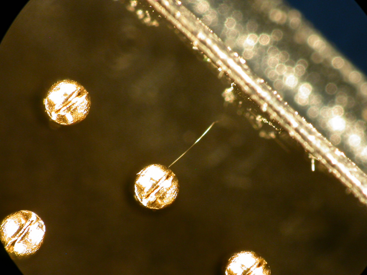
Tin
whisker shorting connector shell to pin
|
Images Courtesy of NASA-GSFC
Connector, D-Sub, Zinc-Plated
Shell
|
Zinc-plated D-Sub Connector Shell with Yellow Chromate Conversion
Coat
|
Zinc Whiskers on D-Sub Connector Shell
|
Zinc
Whiskers on D-Sub Connector Shell
|
|
Zinc
Whiskers on D-Sub Connector Shell
|
Zinc
Whiskers on D-Sub Connector Shell
|
Zinc Whisker
detached from D-Sub Connector Shell
|
Images Courtesy of NASA-GSFC
Connector, Circular,
Cadmium-Plated Shell
The following circular connector shell is
CADMIUM-plated. Connectors like this were used as feed-thrus on a
thermal vacuum test chamber. The cadmium whisker formation on this
shell resulted in shell to pin electrical short circuits that interrupted
testing of space flight hardware.
Source: Anonymous
Connector, Universal Serial Bus (USB),
Video Monitor
Universal Serial Bus (USB) connectors frequently have tin-plated
surfaces. The following photos show tin whiskers forming on USB
connectors used on video monitor circuit card assemblies.
Read
More About these USB connectors from CALCE's www site here:
Images Courtesy of CALCE-University of Maryland
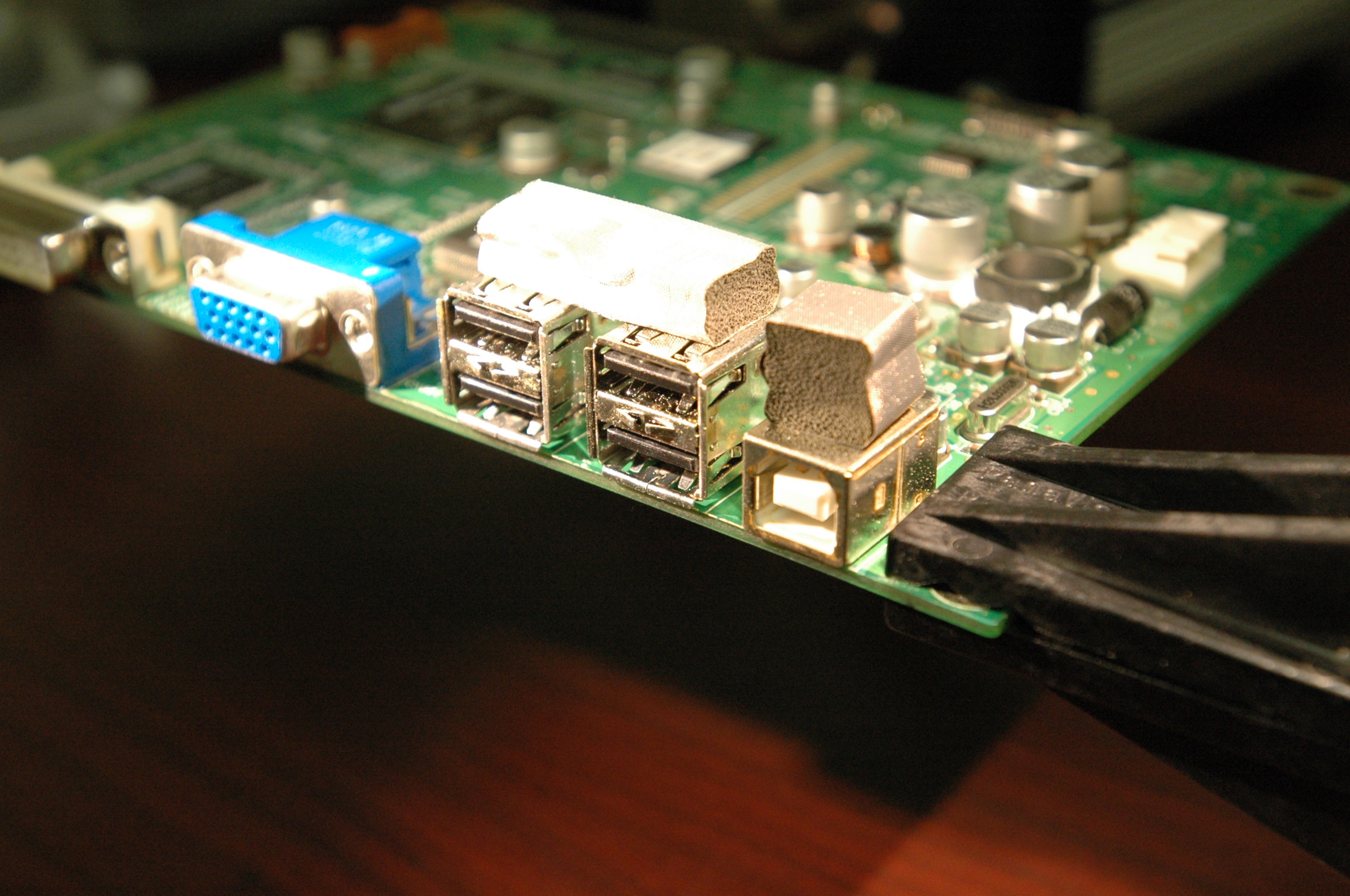
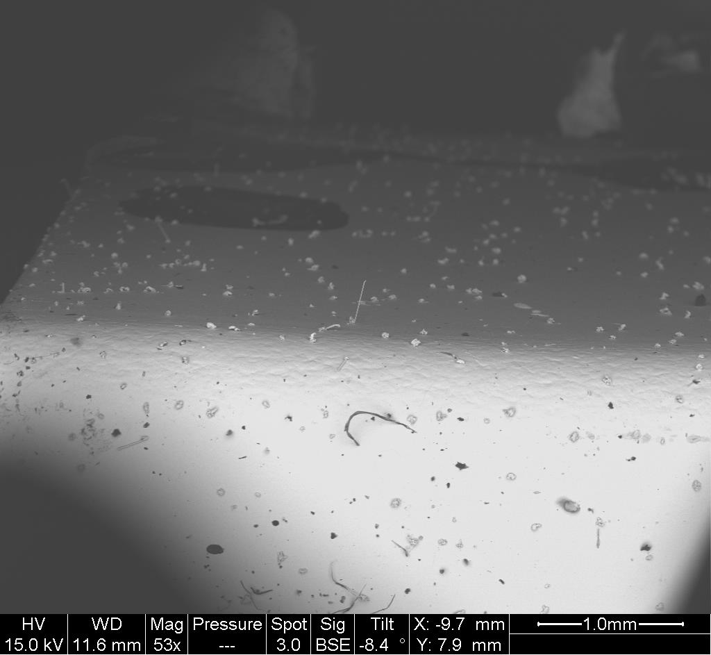
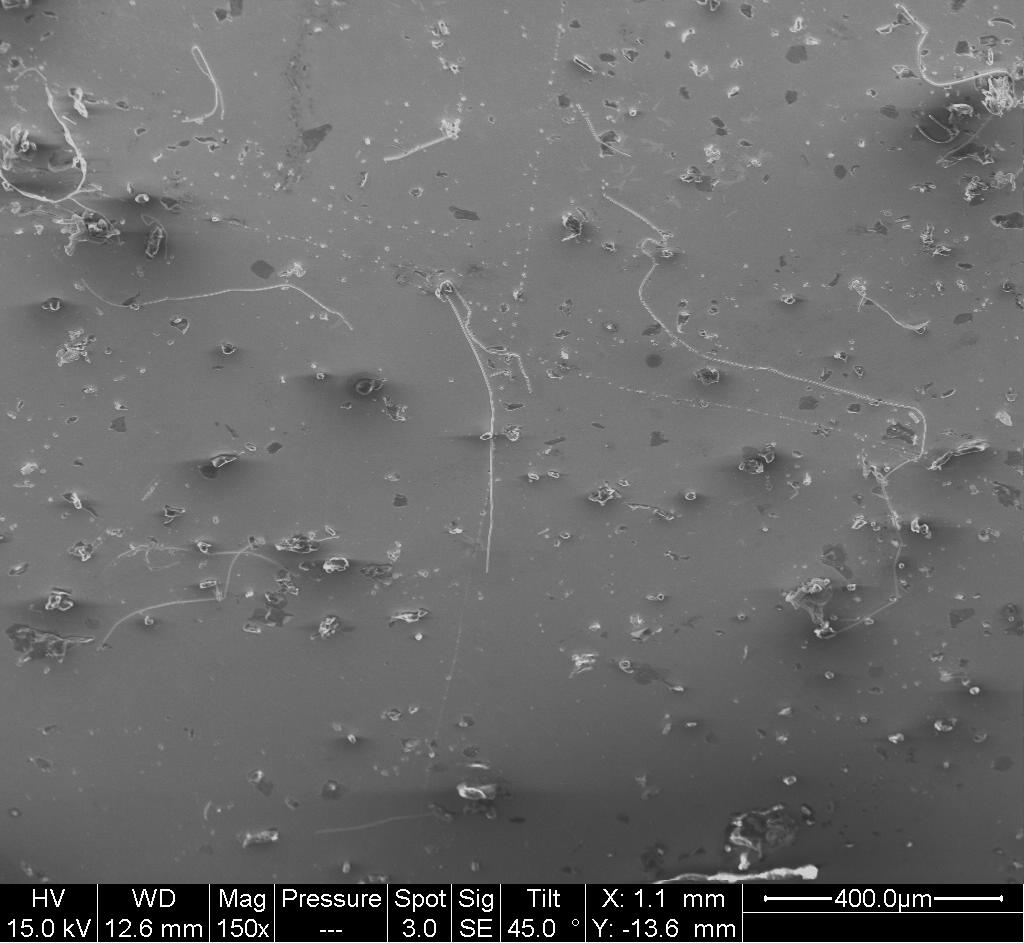
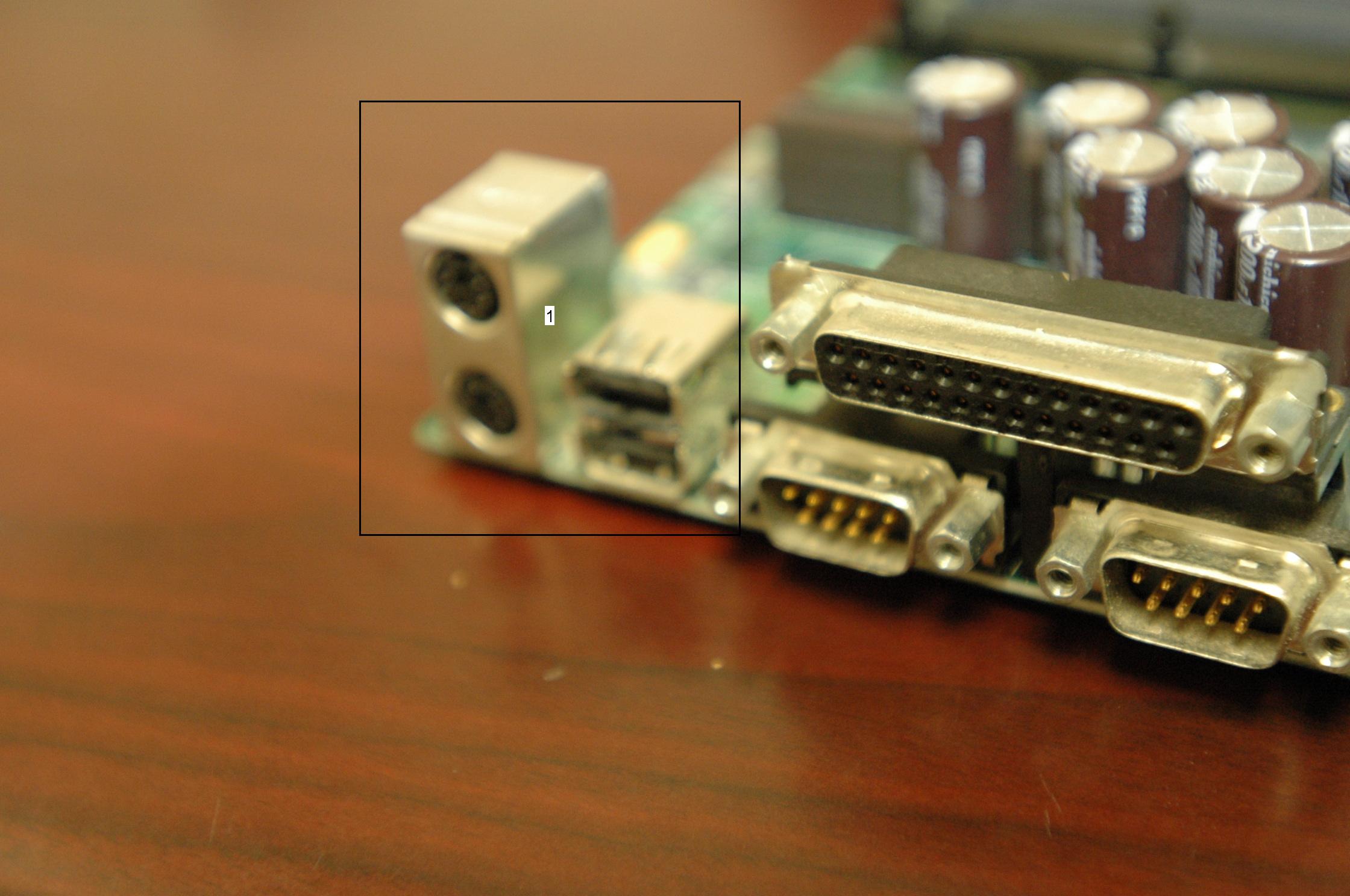
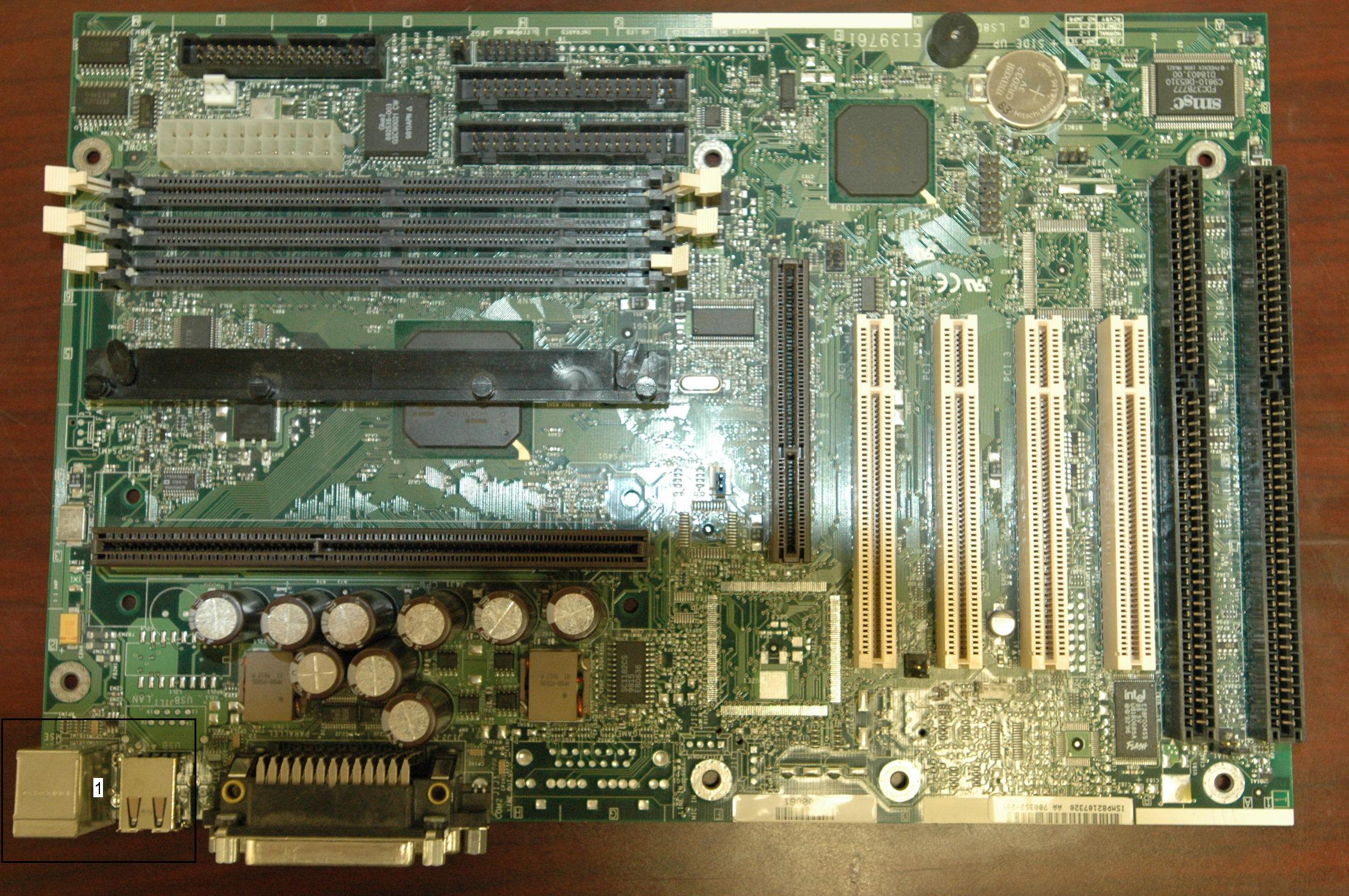
Connector, Universal Serial Bus (USB),
Mother Board
Universal Serial Bus (USB) connectors frequently have tin-plated
surfaces. The following photos show tin whiskers forming on two
different types of USB connectors used on PC motherboard circuit
card assemblies.
Read
More About these USB connectors from CALCE's www site here:
Images Courtesy of CALCE-University of Maryland
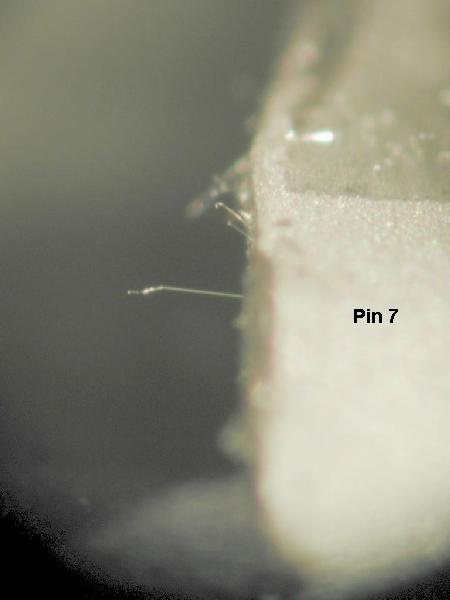
Connector, Octal Type
The connector below is an octal type connector with
circular cross-section pins on the plug-in side (left side of first image
below) and rectangular cross-section pins on the right angle mount
solderable contacts (right side of first image). The pins are pure
tin-plated. Tin whiskers were found on the rectangular cross section
pins while performing an inspection of a module reported to have failed in
a commercial electric power utility application due to tin whisker shorts
originating from a microcircuit also used in this assembly.

Octal type connector with pure tin plated pins |
Wide view of pin shows some tin whiskers. |
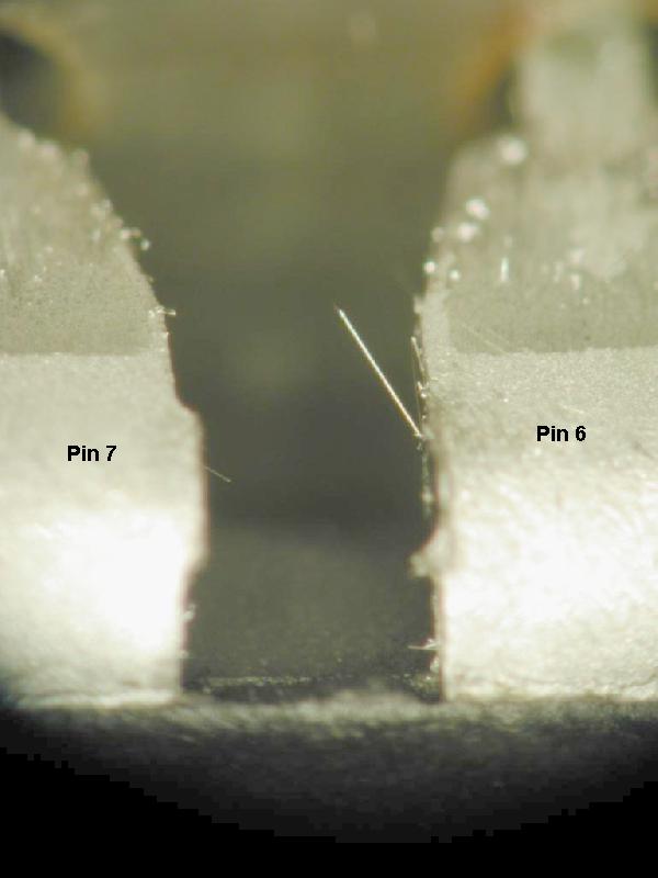
Tin whisker on pin |
c
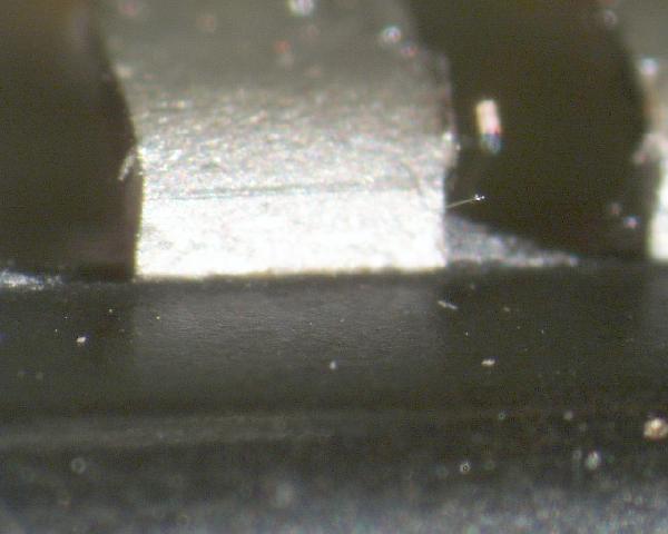
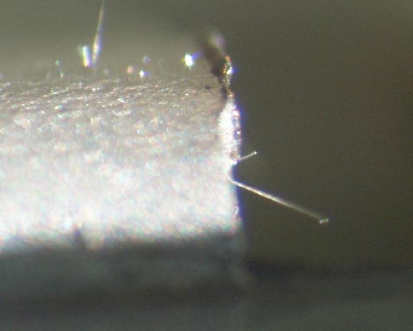
Tin whisker on
pin |
Tin whisker on
pin |
|
Images Courtesy of NASA-GSFC
Crystal
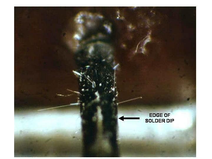
Crystal, Tin-Plated Case
The leads on this crystal are made of Kovar (Fe-Ni-Co
alloy) with a Nickel barrier layer having a final pure tin finish.
Prior to installation the user dipped the leads into tin-lead solder to
improve solderability. However, a small portion of the leads (close
to the package) remained pure tin finish. This pure tin region
produced tin whiskers that shorted the lead to case causing field failures
Read More about this
Crystal and the Benefits & Limitations of Hot Solder Dip to Mitigate
Tin Whisker Growth
Source: Anonymous
Discrete
Semiconductors
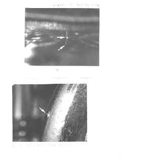
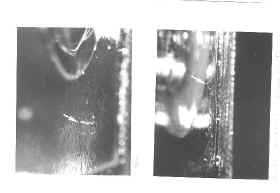
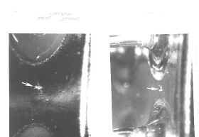
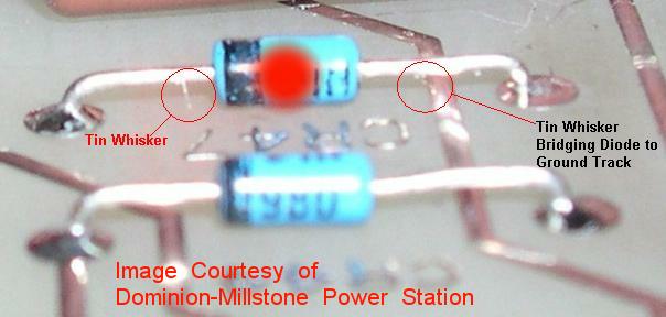
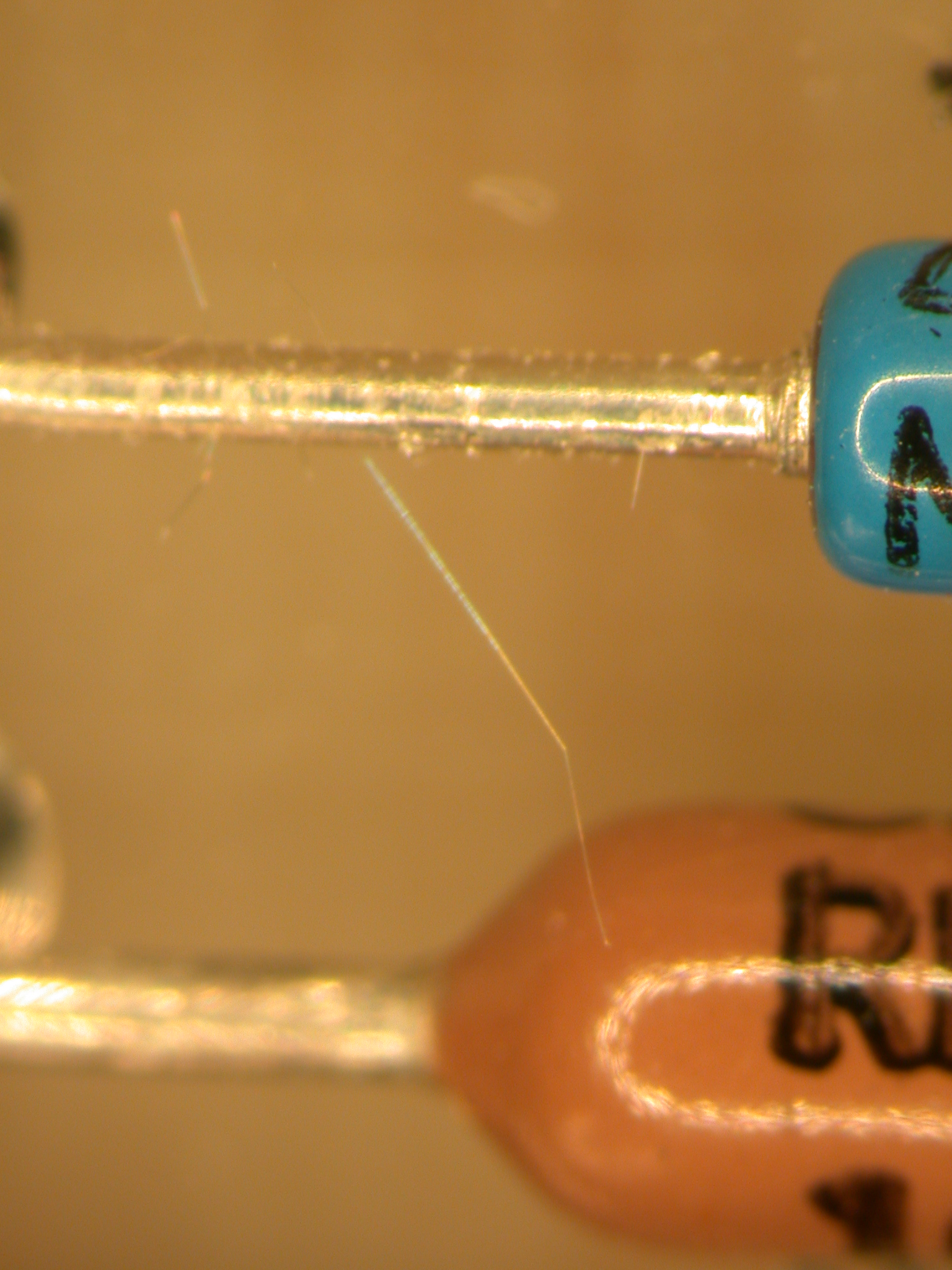
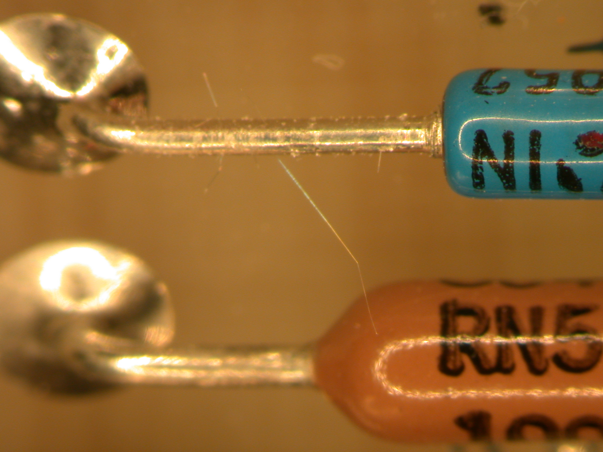
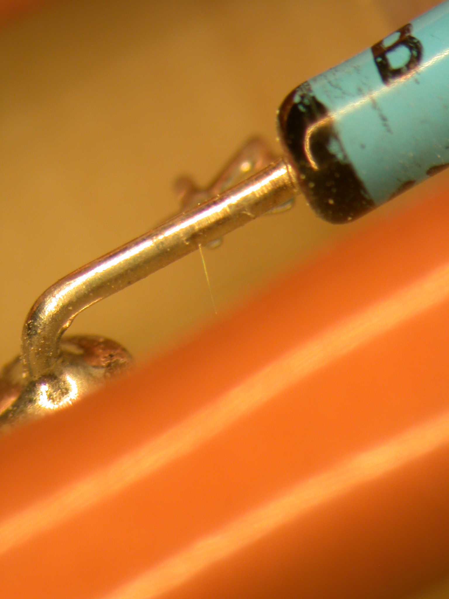
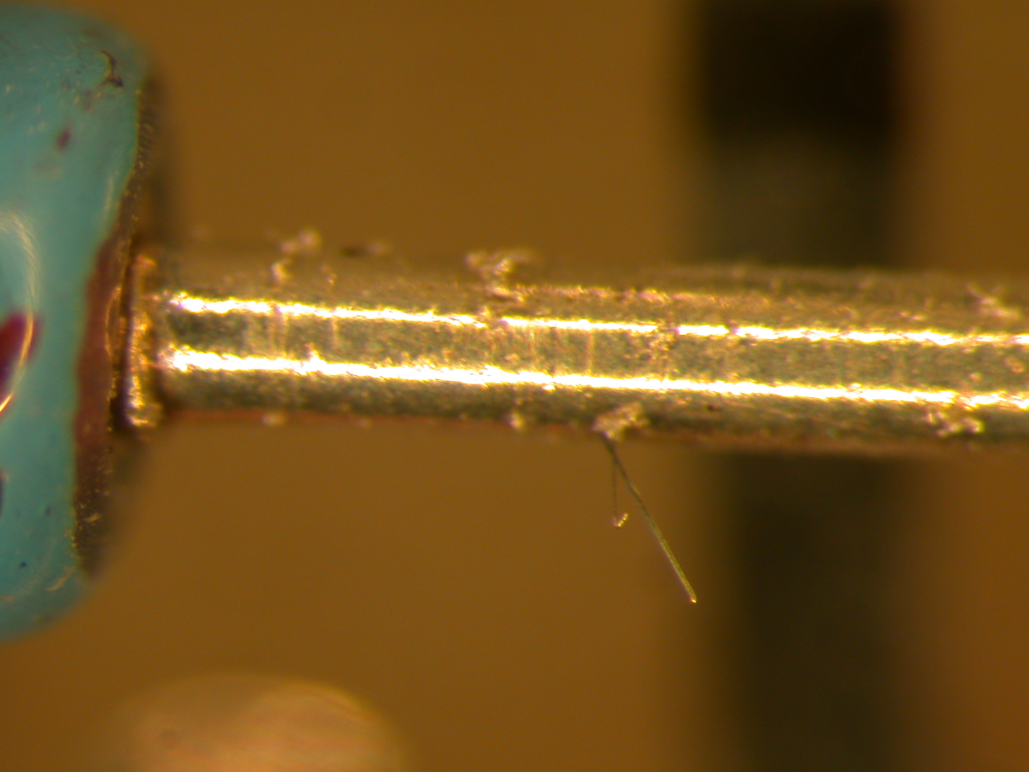
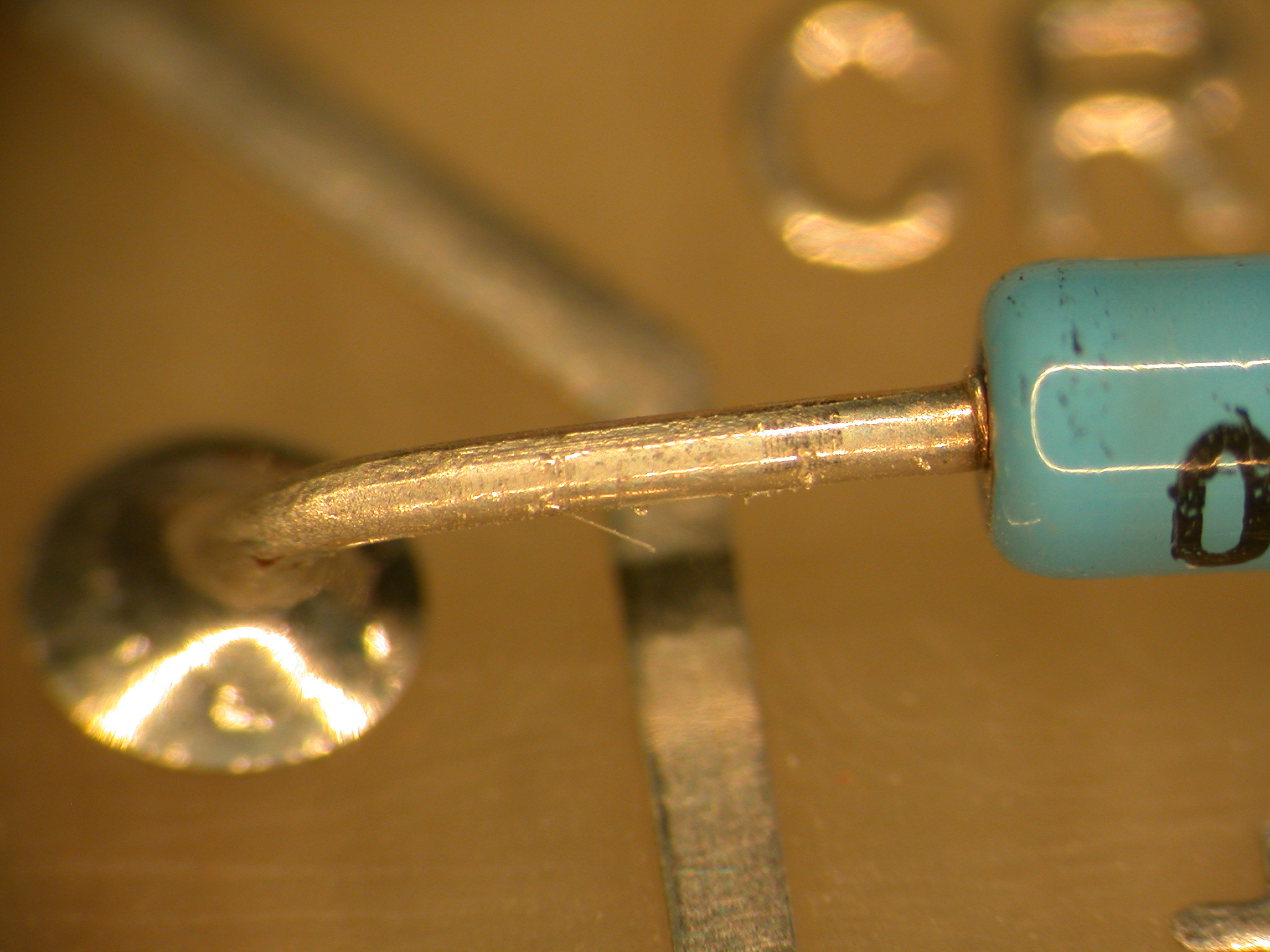
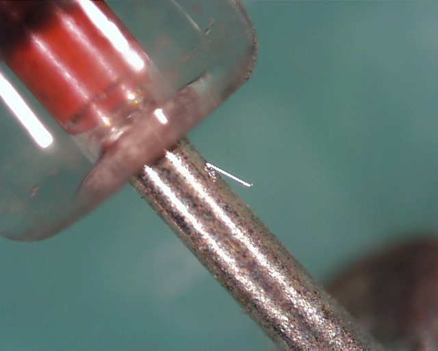
Diodes, Axial
Lead, Tin-Plated
Axial-leaded diodes having tin-plated terminals have
exhibited tin whisker formation.
In 2005 the Dominion Millstone Nuclear Power Station experienced a reactor
shutdown that was traced to an inadvertent alarm signal produced by a tin
whisker short circuit from diodes like these.
Read
the article here:
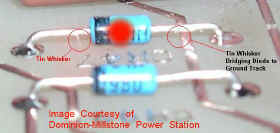
Image Courtesy of Dominion-Millstone Power Station
Images Courtesy of T. Riccio/STPNOC
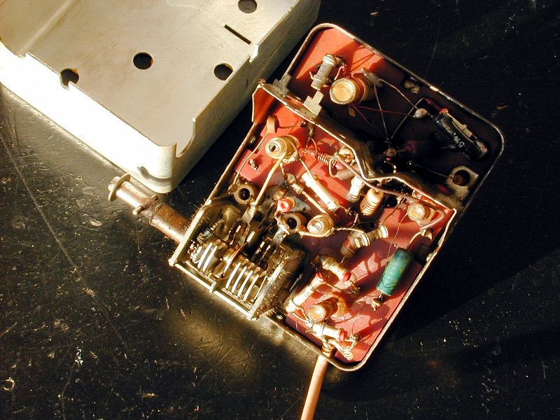
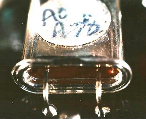
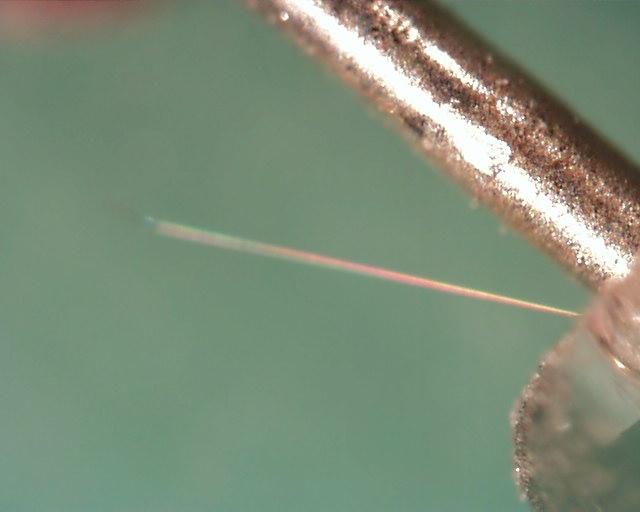
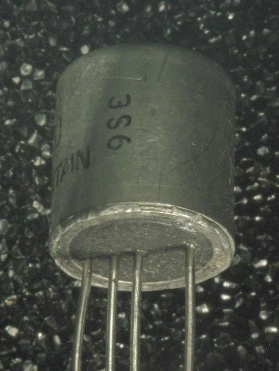
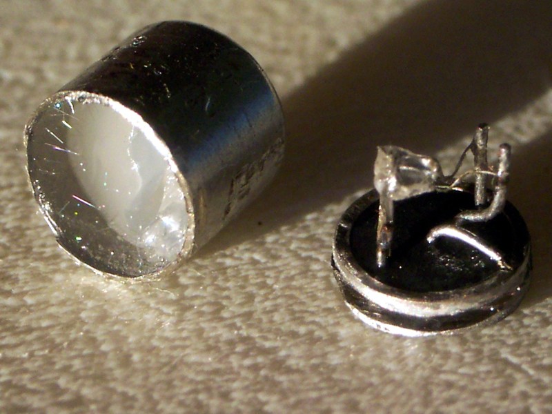
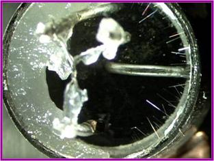
Transistor, Metal Case,
Tin-Plated
The package of these transistors used extensively in
vintage radios is tin-plated. Tin whiskers growing on the internal
surfaces of the package have produced short circuit failures of these
transistors.
Read
More about these Transistors and how a community of vintage radio
collectors have combated the mysterious source of electrical short circuit
failures.
Images Courtesy of NASA-GSFC and Paul Stenning
Electromagnetic
Relays
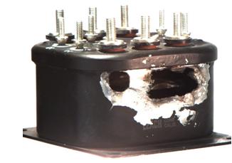
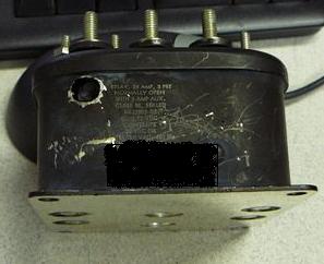
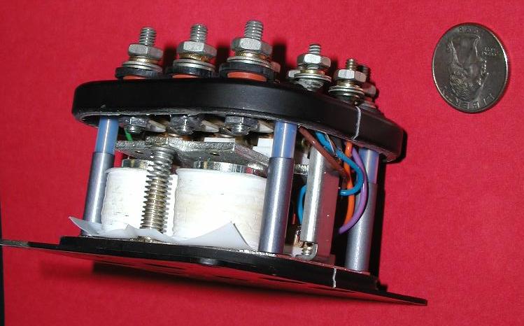
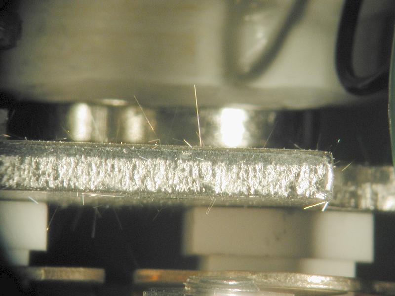
Relay, Electromagnetic,
Tin-Plated Steel Armature
The hermetic relay shown below (age ~14 years) has an iron
armature that has been plated with PURE TIN. The armature is
INTERNAL to the packaged relay and cannot be seen by the user unless the
device is destructively opened for analysis. As noted by the images,
numerous tin whiskers are clearly visible (even via naked eye inspection)
growing from the armature. Some whiskers are approaching 3 mm in
length which is more than sufficient length to create a short internal to
this device.
Read
More About the Failures Attributed to Metal Vapor Arcing initiated by tin
whiskers inside this relay.
See
a Video of Whiskers Inside this Relay Demonstrating Extreme Flexibility
When Subjected to Air Currents
Specimen and damaged
relay photos supplied by G. Davy/Northrop Grumman
Whisker Photos courtesy of NASA GSFC
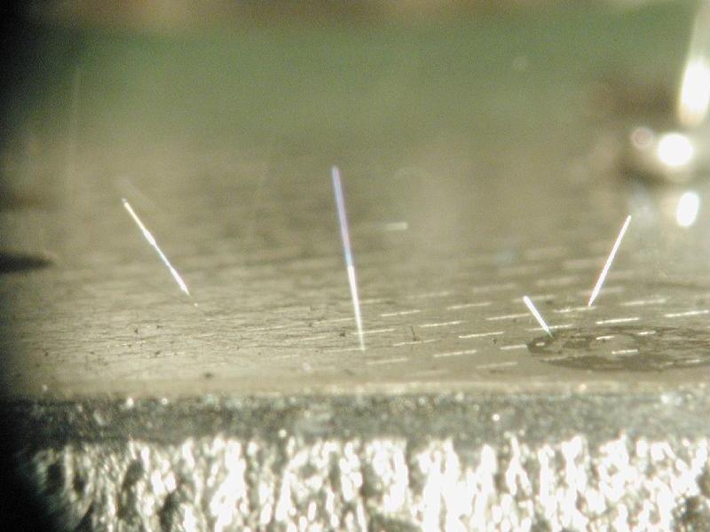
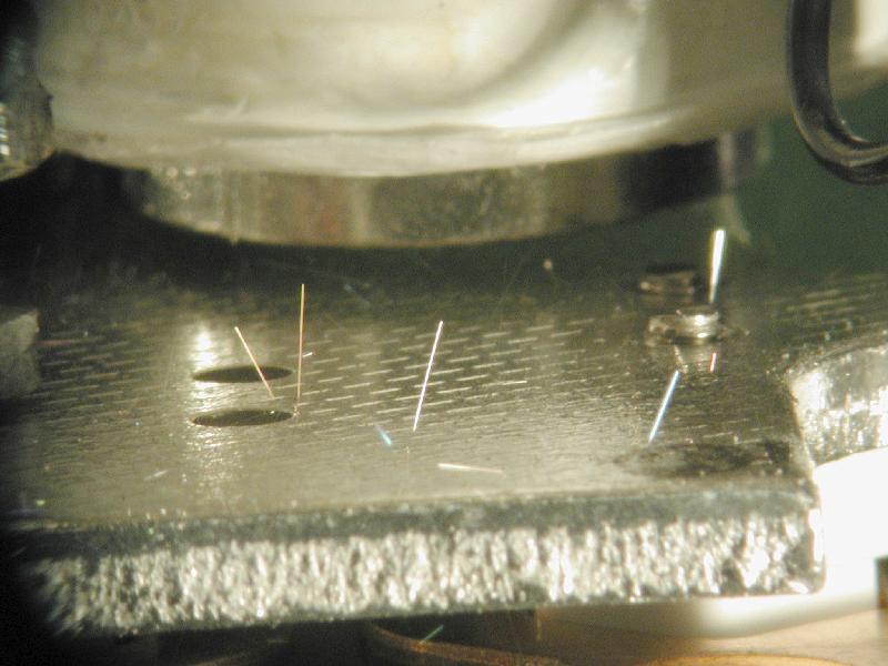
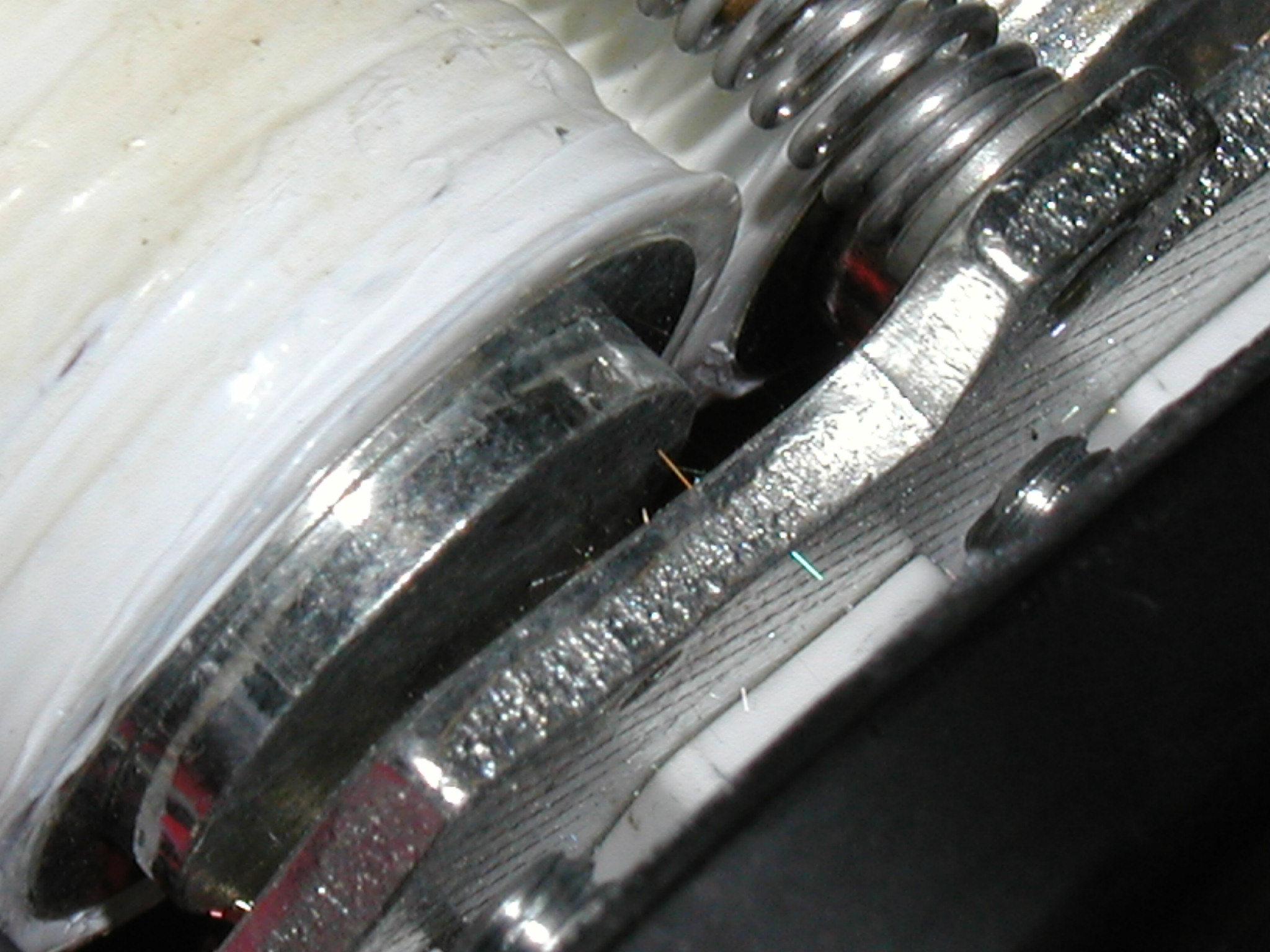
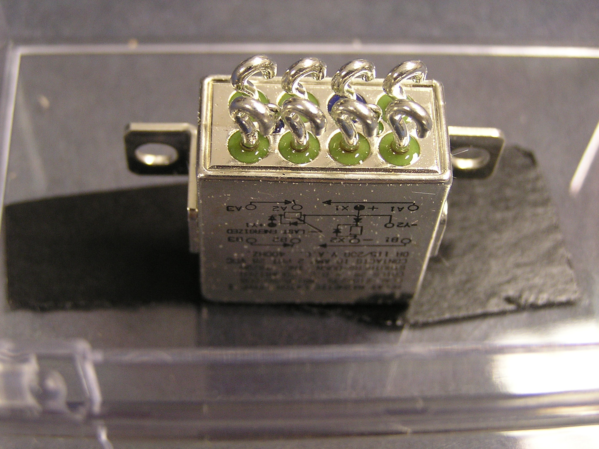
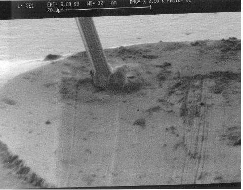
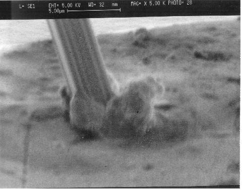
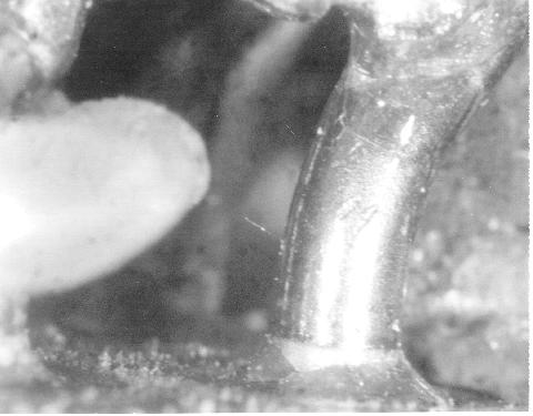
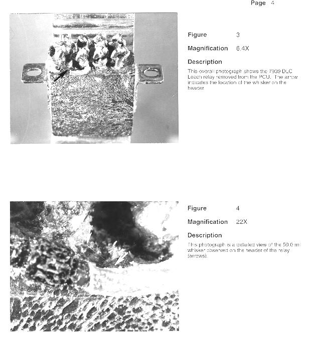
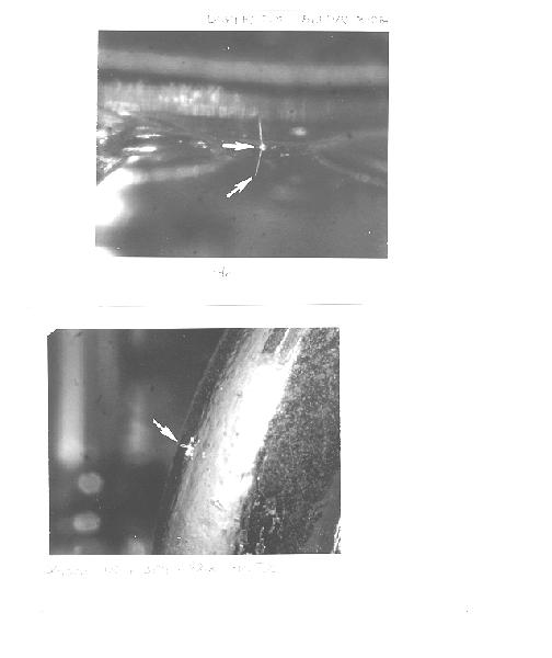
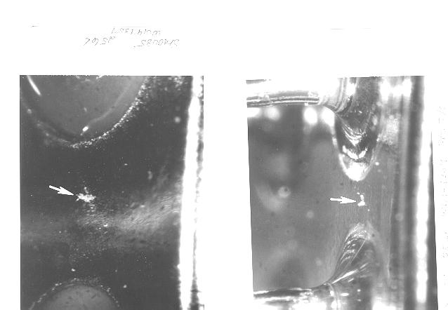
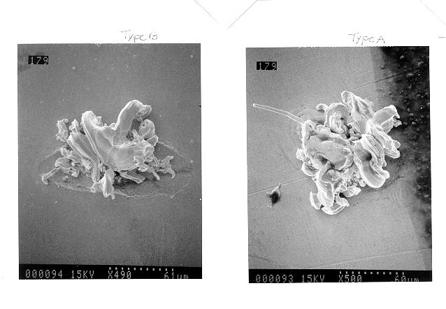
Relay, Electromagnetic,
Tin-Plated Case, Terminals & Header
The Relays shown below
are plated with pure tin. This plating exists over the entire case,
header and the hook terminals that will normally have stranded wire soldered to
the end of the hooks. Whisker shorts can occur due to whiskers
growing from either the case, header or the terminals. Even when
terminals have wire soldered to the hooks, whiskers have been observed
growing from the base of the terminals near the glass to metal seals.
Images
Courtesy of NASA-GSFC

Tin whiskers on terminals |

Tin whiskers on terminals
|
Tin whiskers on terminals |
Tin whiskers near glass seal
|
Tin whiskers near glass seal |
Close up of Tin whisker growths |
close up of Tin whisker growths
|

Tin whiskers near glass seal
|
Images
Courtesy of Space Systems Loral
Hybrids and
Microcircuits
Hybrid Microcircuit
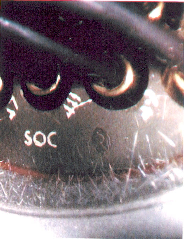
The photo below is of the package lid of a hybrid microcircuit.
The lid was plated with pure tin. This whisker was found growing on the on
the surface of the lid that was facing INSIDE the of the device.
Other whiskers were also found on the lids with some as long as 2
mm.
In previous (unrelated) reports, whiskers similar to the one shown below
on hybrid package lids have been reported to cause field failures in
Phoenix Missiles1 and F-15 radar systems2
1) L. Corbid, "Constraints on
the Use of Tin Plate in Miniature Electronic Circuits", Proceedings
3rd International SAMPE Electronics Conference, pp.
773-779, June 20-22, 1989.
2) B. Nordwall, "Air Force
Links Radar Problems to Growth of Tin Whiskers", Aviation Week and
Space Technology, June, 20, 1986, pp. 65-70
Images
Courtesy of NASA-GSFC
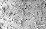
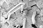
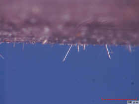
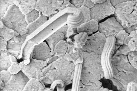
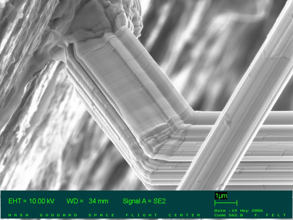
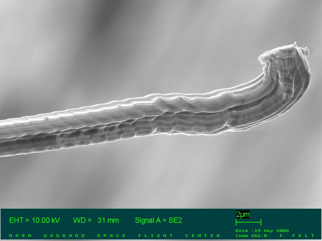
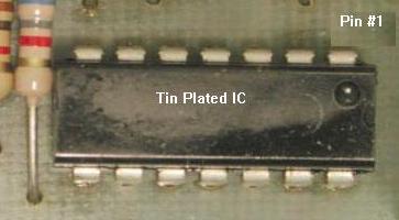
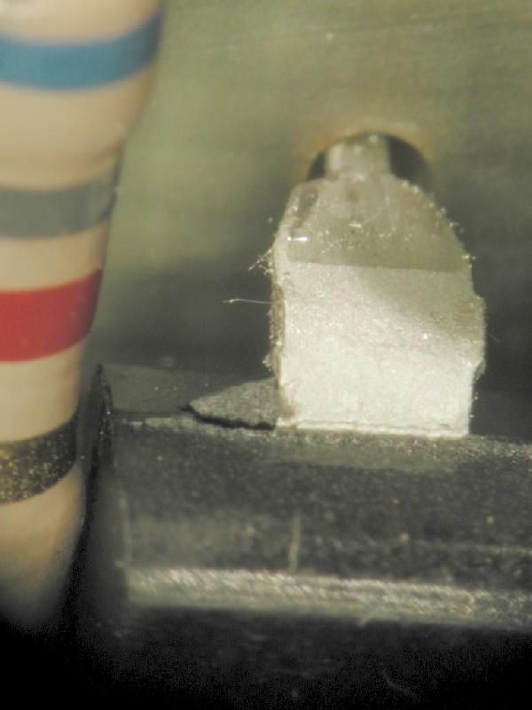
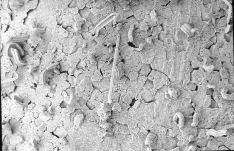
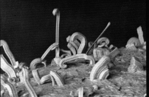
Tin Whiskers growing on a MATTE tin-plated copper leadframe commonly used in the manufacture of 28 pin small outline integrated circuit (SOIC) leadframe after 3 years of ambient storage.
Photos
Courtesy of Peter Bush (State University New York at Buffalo)
Resistors
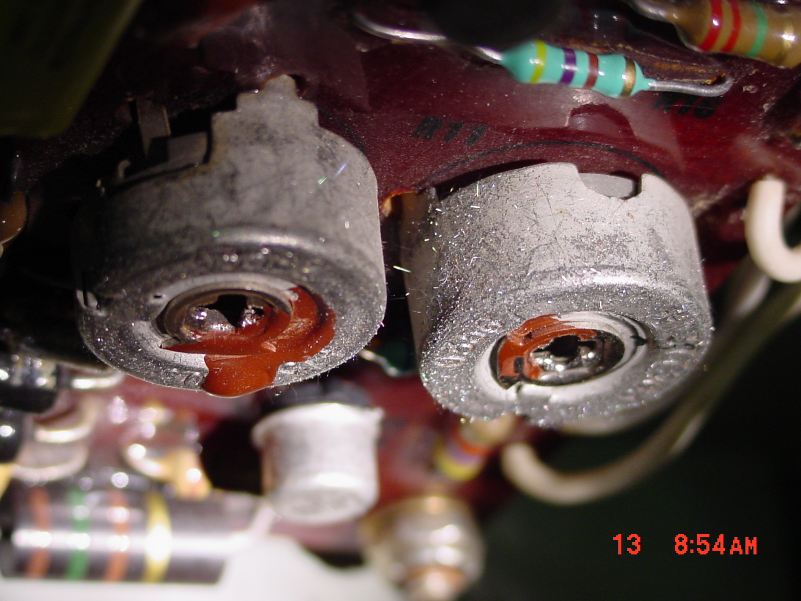
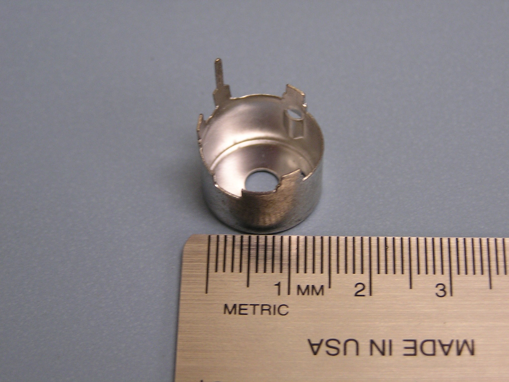
Potentiometers
In 2005 Westinghouse Nuclear published a service
bulletin describing how metal whisker formation on certain
potentiometer cans could produce power supply interruptions.
Images Courtesy of T. Riccio/STPNOC
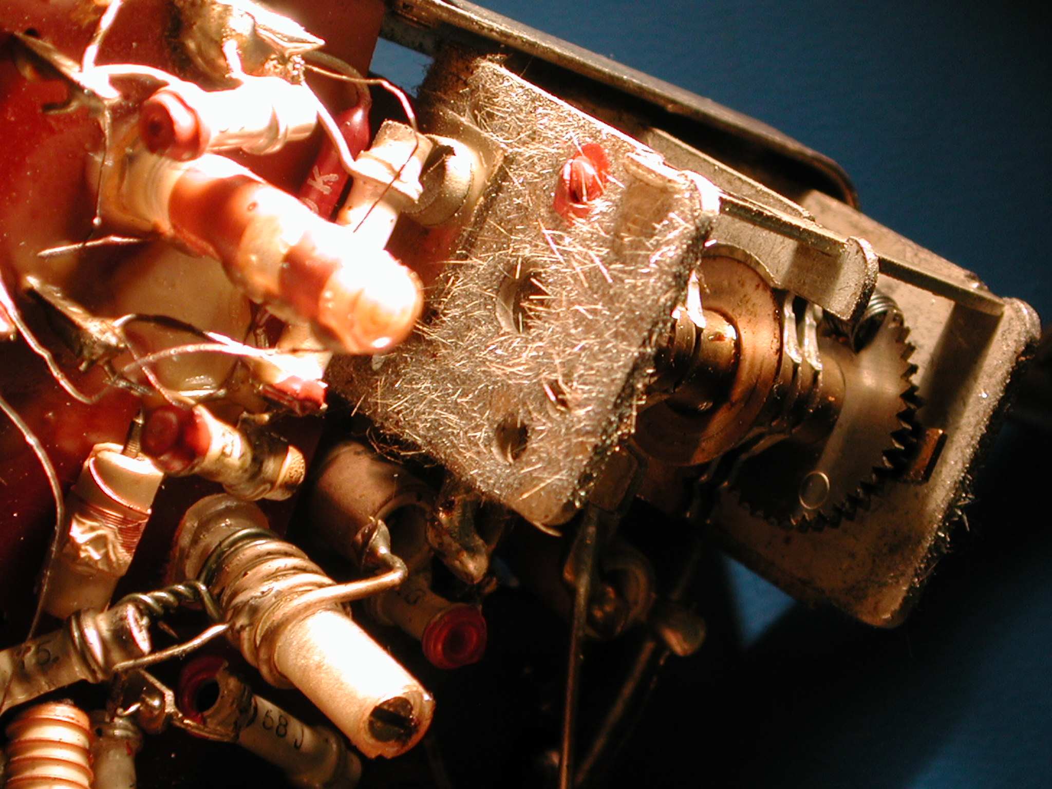
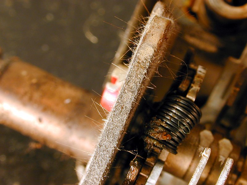
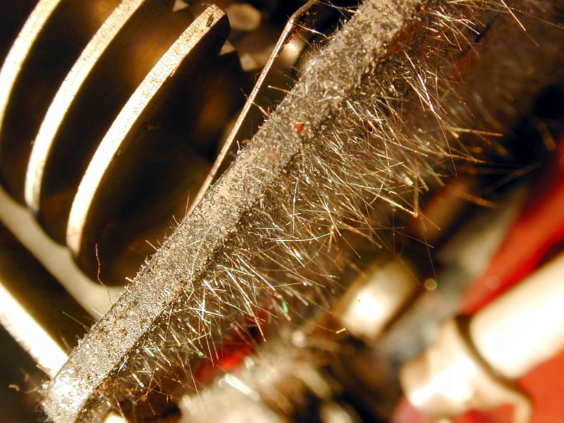
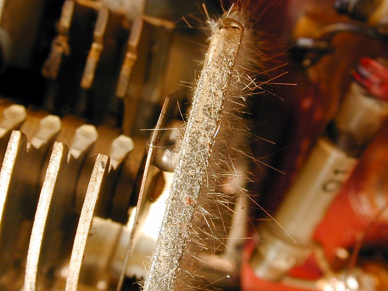
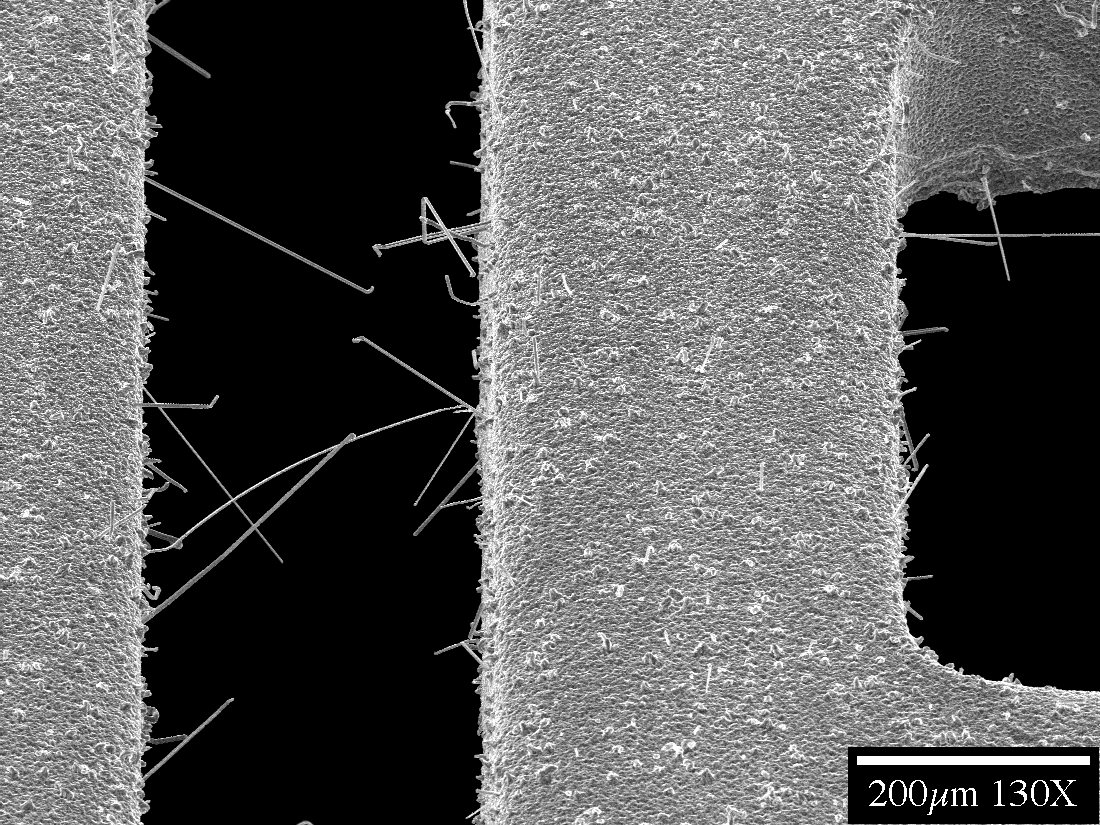
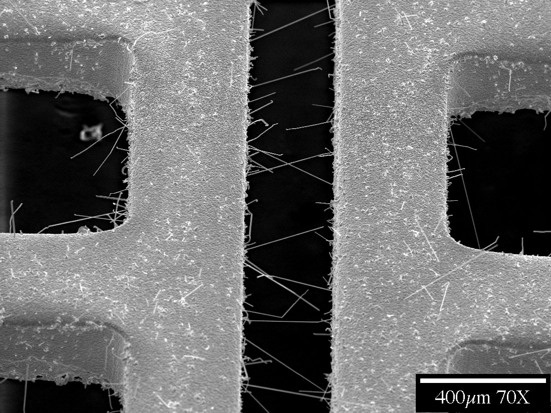
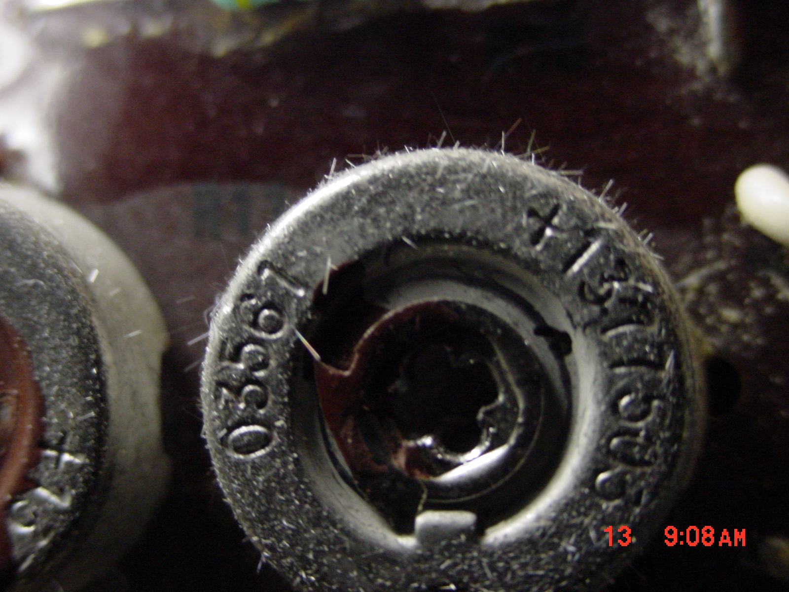
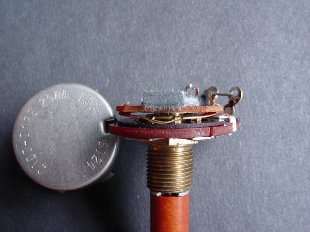
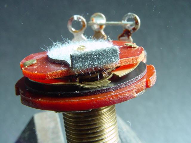
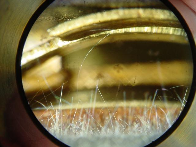
Potentiometer,
Internal Structures
The following potentiometers were used as calibration pots
in oscilloscopes from the 1970s. Mis-operation of the oscilloscope
were diagnosed to be the result of the metal whiskers growing from the
internal components of the potentiometer shorting its case to the wiper..
Images courtesy of Alan Douglas/UK
Vintage Radio Forum
Transformers
Transformer Cans
The supplier of these transformer cans originally supplied
them with tin-lead (Sn-Pb) finishes. In response to international
legislation (e.g., RoHS) they switched to pure tin coatings without
changing part numbers nor issuing a product change notice to their
customers. Fortunately, for the user who provided NASA Goddard with
these samples, the external appearance of the cans was different enough to
encourage him to provide them to us for a closer look. Thanks to Steve
Battel for sharing these samples with us.
See
a Video of these transformer cans
Images
Courtesy of NASA-GSFC
After receiving these pictures of concern the supplier
responded:
"We appreciate your loyalty for so many years and your
email concerning the whisker growth. The push to be RoHS compliance has caused us to switch our plating process
and introduce new materials that are environmental friendly but they in
turn created other problems. I sent your concerns to our product manager and I hope we can do something
about it."
Wave
Guides
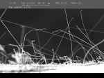
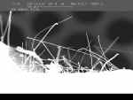
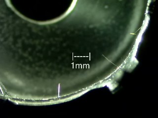
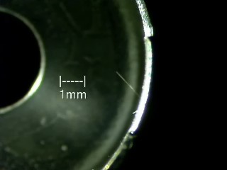
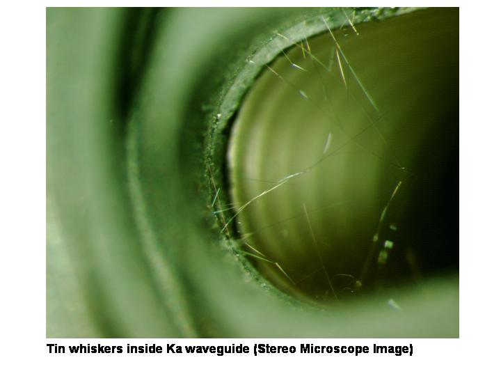
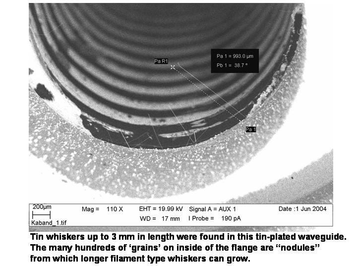
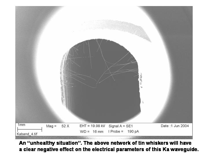
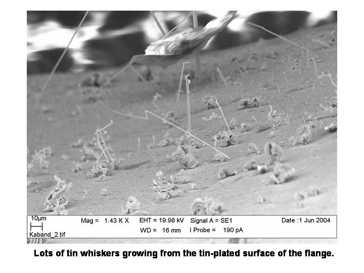
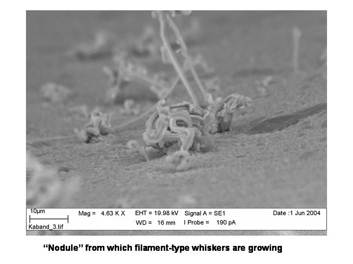
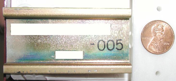
Wave Guide, Tin-Plated Flange (Documented in 2004)
The images below depict tin whiskers found growing from
the tin-plated flange of a Ka band waveguide. The high density of
whiskers, some approaching 5-mm long, were found within several weeks of
receipt of product by the waveguide user. In the end application whiskers
of this size and density produced signal reflections and losses that
affected the electrical performance of the waveguide.
Read
More about the Tin Whiskers Found on this Wave Guide
Images
Courtesy of Ingemar Hernefjord
Mechanical Hardware
and Structures
Bus
Rails and Bus Bars
Bus
Rail, Zinc-Plated
Steel (Documented in 2001)
The images below depict ZINC
whiskers found growing on a zinc electroplated steel bus
rail. This rail also has a yellow chromate finish which obviously
did not inhibit whisker formation. Whiskers up to several
millimeters long were observed. The user of this bus rail determined
the zinc whiskers were the root cause of catastrophic electrical shorting
failure during a thermal vacuum test.
ADDITIONAL
GALLERY of Zinc Whisker Photos on this Bus Rail
Source: Anonymous
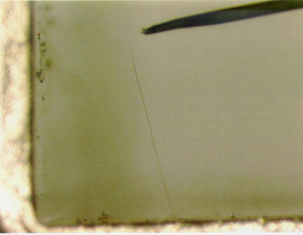
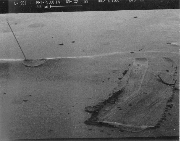
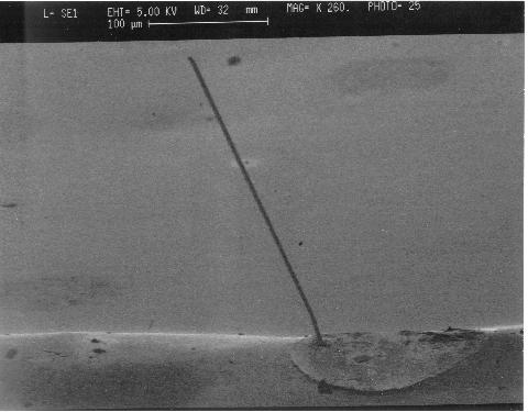
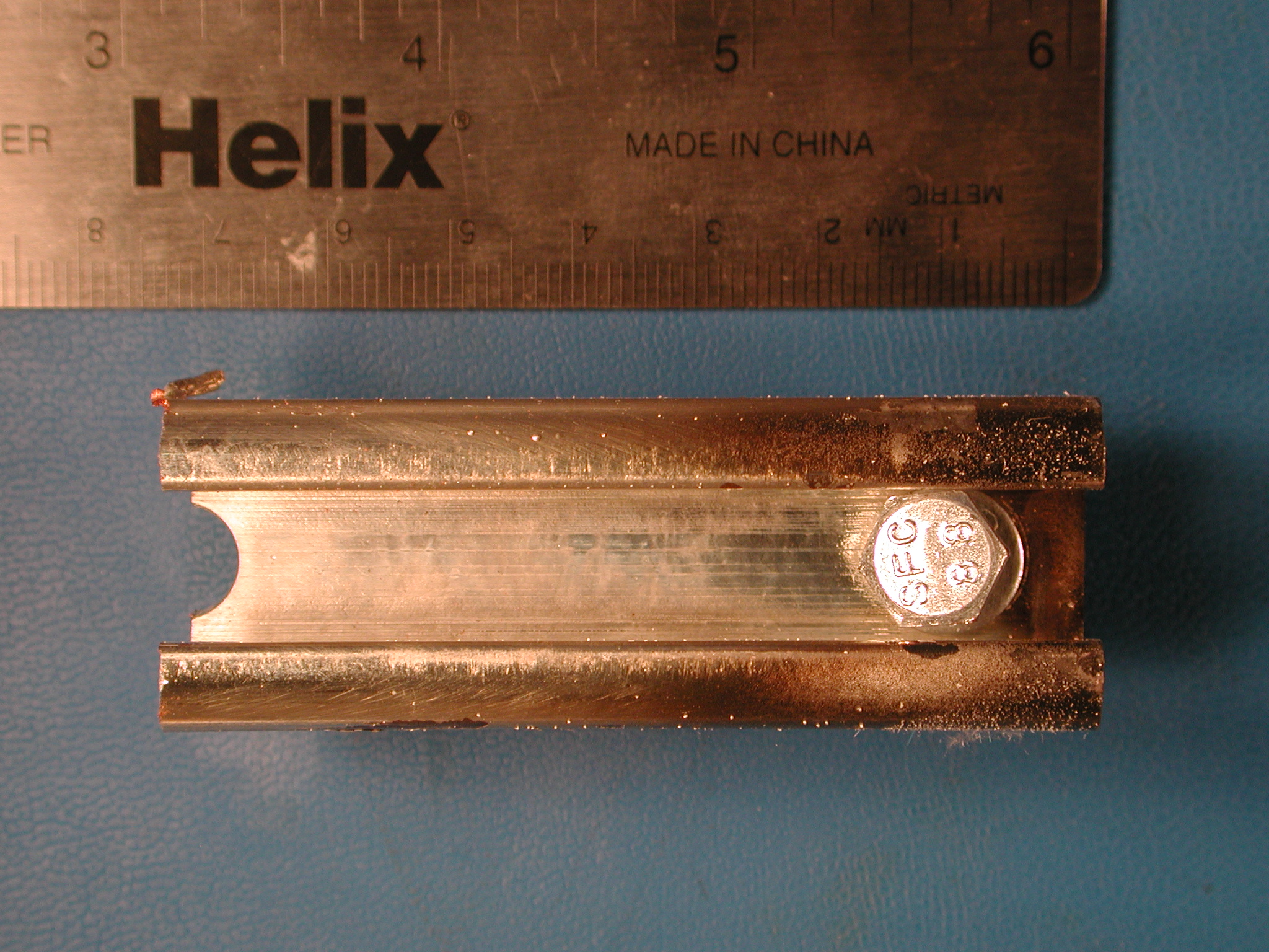
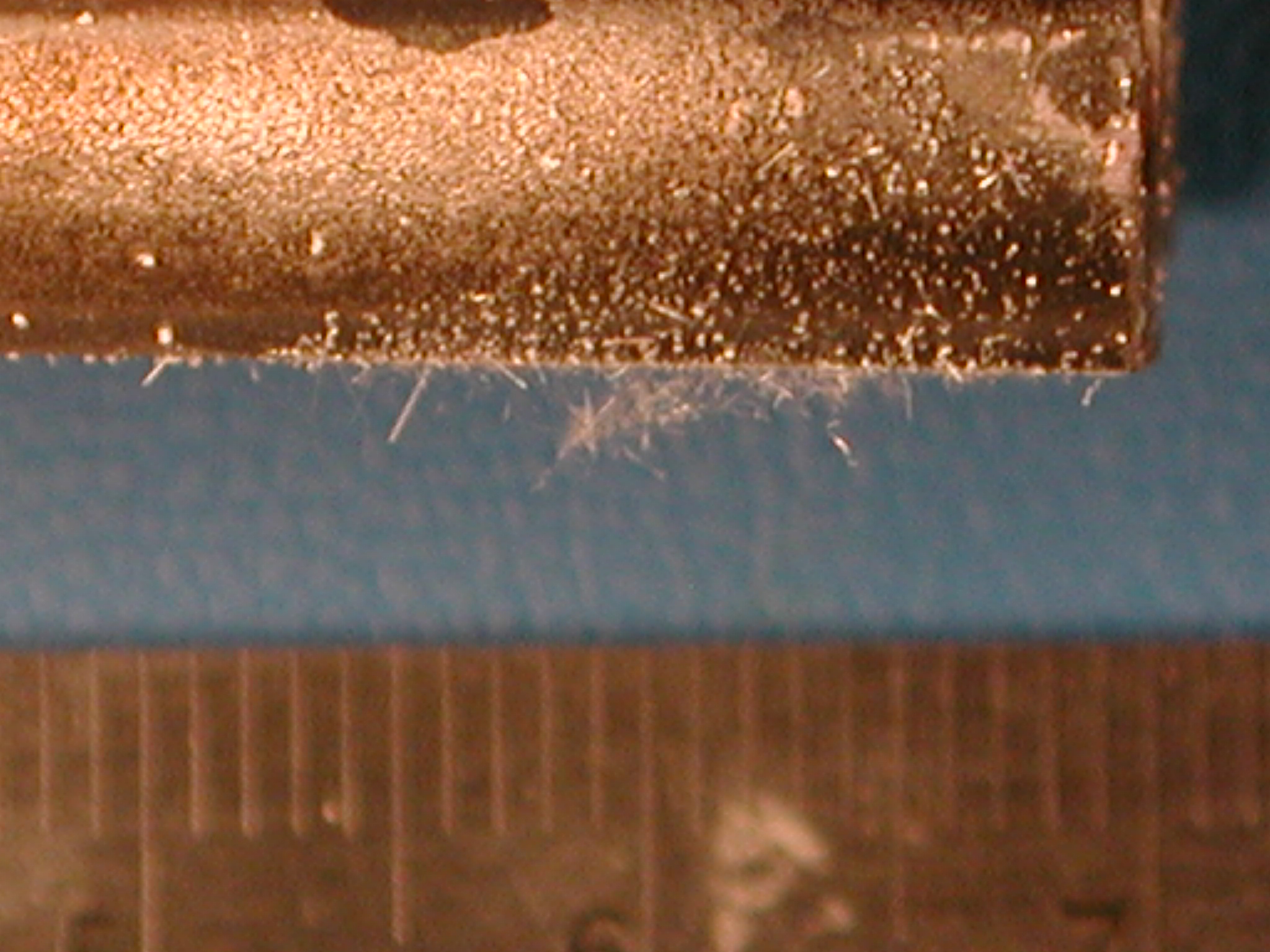
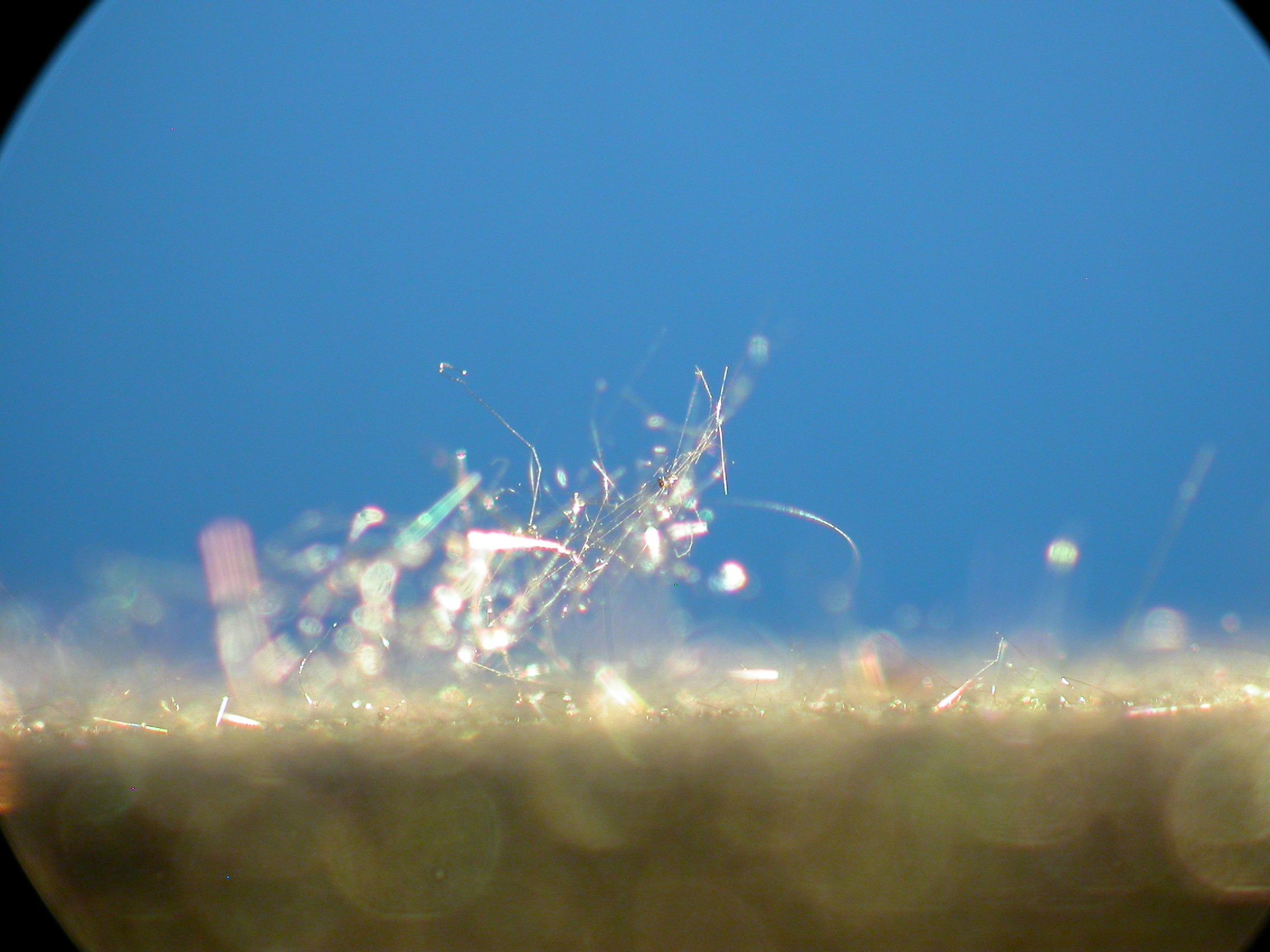
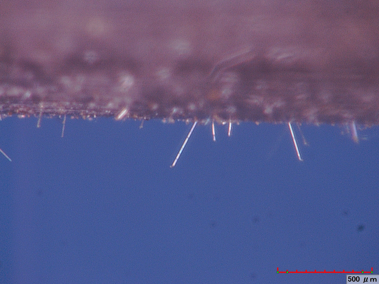
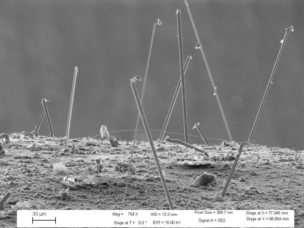
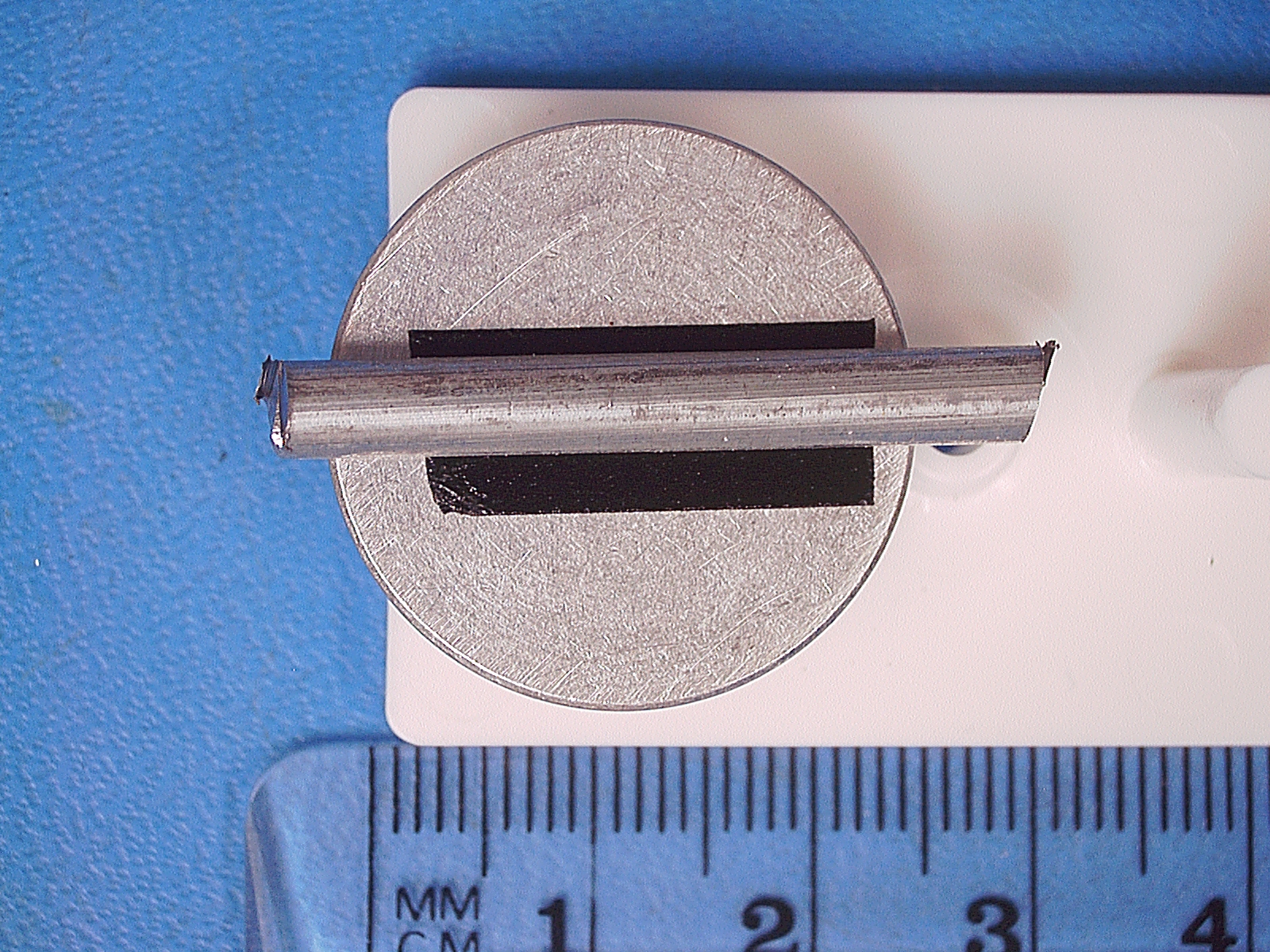
Bus Bar, Tin-Plated Copper
The following bus bar is made of copper that has been tin-coated.
It was installed in manufacturing equipment used by a large paper mill in
Sweden. It is suspected that tin whisker growth from bus bars like
this one may have initiated Metal Vapor Arcs on at least three separate
occasions resulting in significant damage and equipment down-time.
Read more about the tin whiskers on this bus bar
Sample provided by Anders Johansson
Optical Photos courtesy of NASA-GSFC
SEM photos courtesy of Lyudmyla Panashchenko
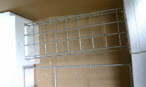
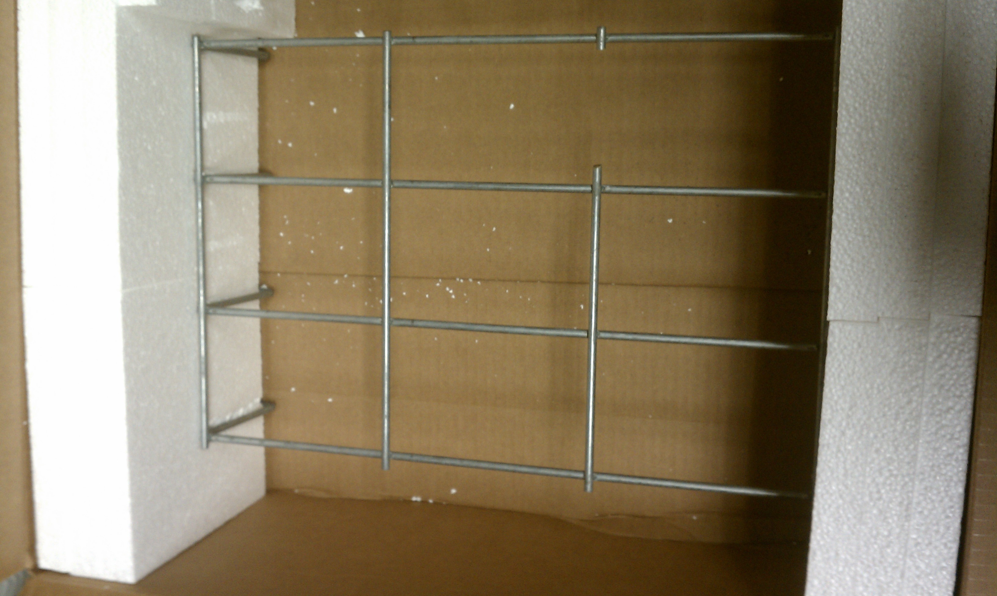
Cable
Trays
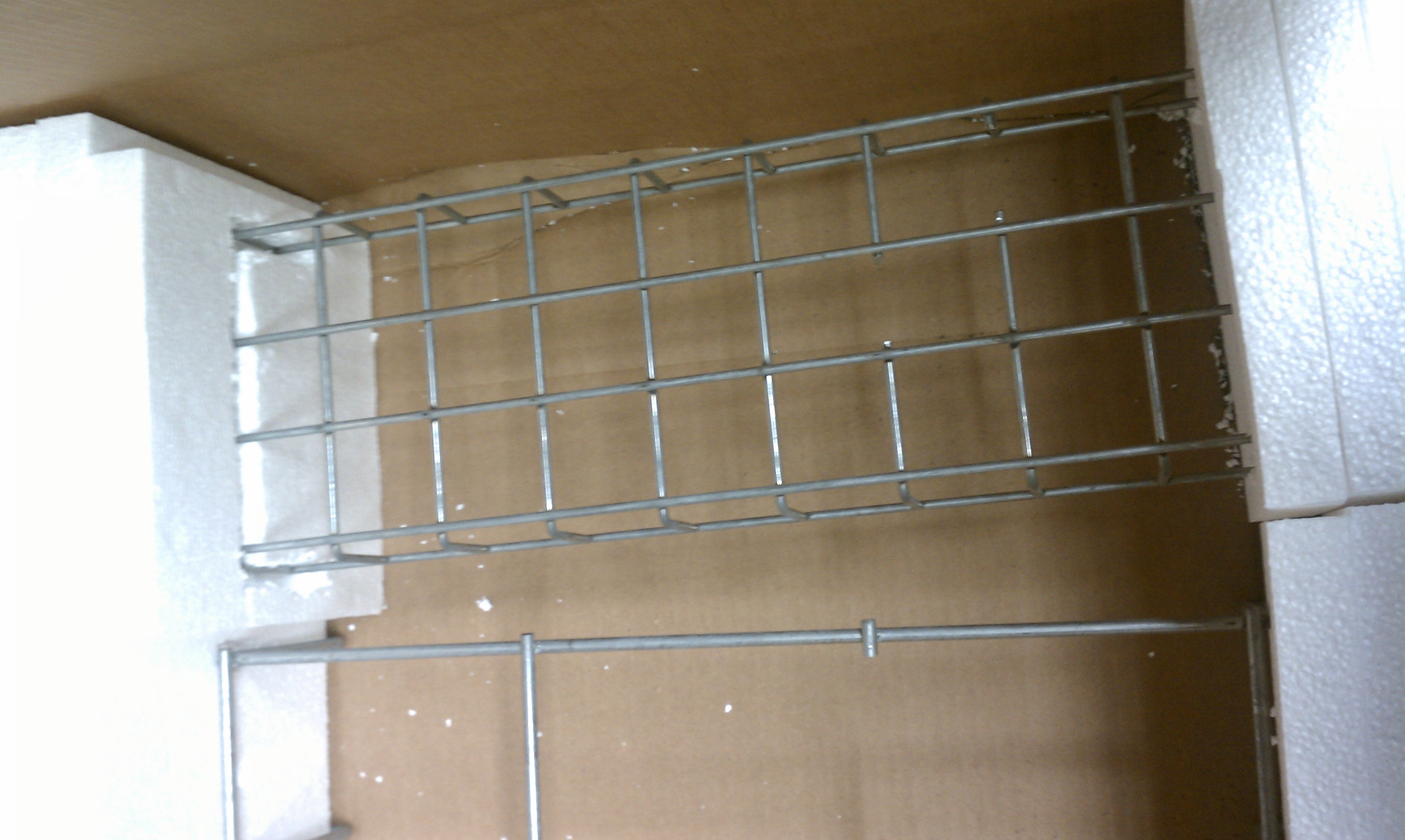
The following images document the growth of zinc
whiskers from zinc-coated steel wire cable trays made by
two different manufacturers. Each cable tray is reportedly made from
"pre-galvanized"
steel where pre-galvanizing indicates that the steel wire was hot
dip galvanized (i.e., zinc coated by immersion into molten
zinc) and then the cable trays were made by welding together the already
zinc-coated steel wire into the final cable tray structure.
A summary report documenting the zinc whisker growths on each cable
tray can be found here:
Zinc
Whiskers on "Cable Tray #1"
Zinc
Whiskers on "Cable Tray #2"
| Cable
Tray #1 |
 |
 |
 |
 |
 |
 |
| Cable
Tray #2 |
 |
 |
 |
 |
 |
 |
Samples provided by Greg Camburn
Analyses by NASA - GSFC
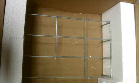
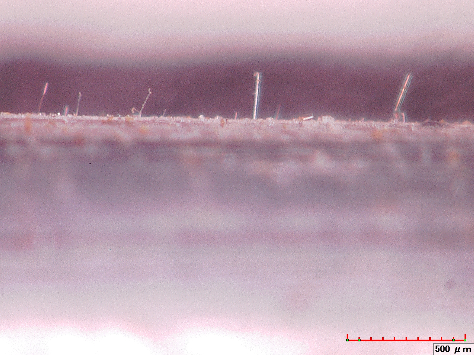
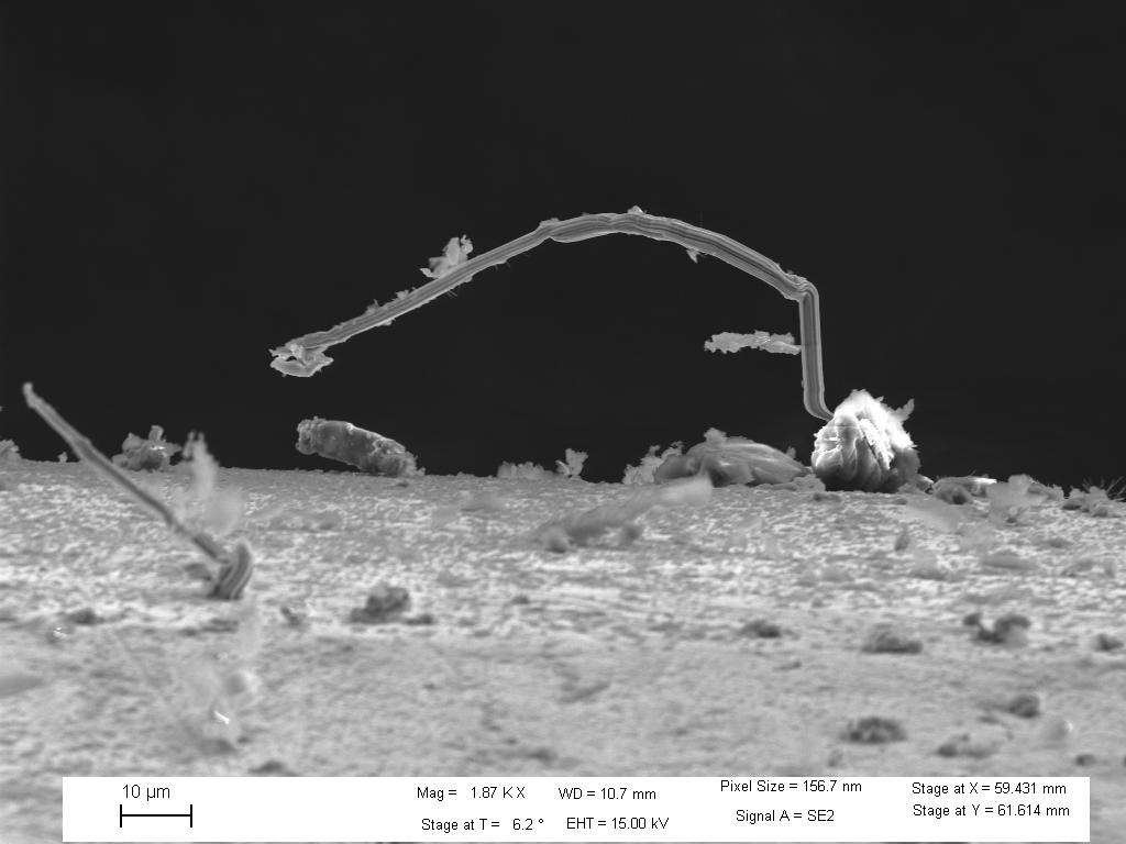
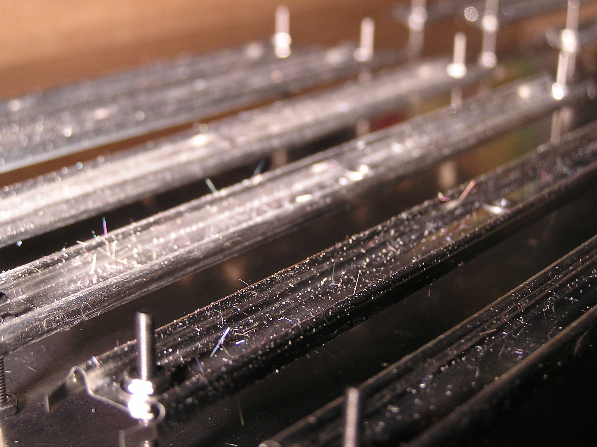
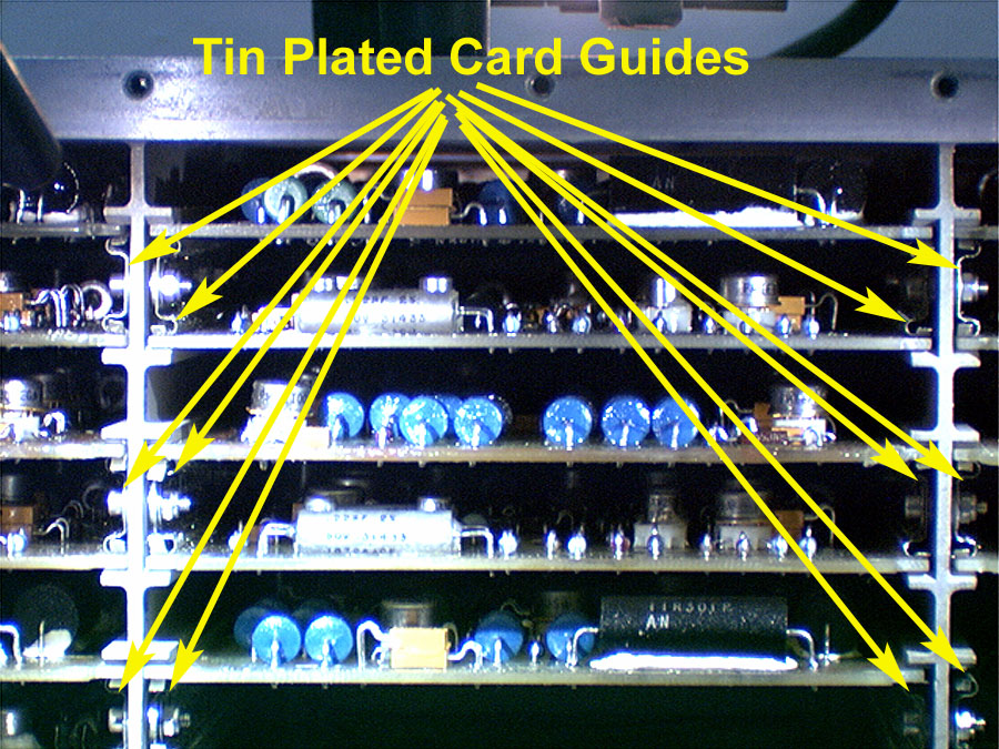
Card Guides
Card Guides, Tin-Plated Beryllium
Copper
|
|
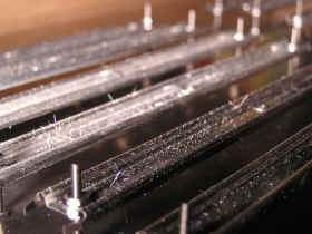
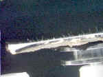
In March 2006 the Space Shuttle Program discovered a
massive tin whisker infestation on the printed circuit board "card
guides" (aka card rails, card retainers) used to guide and hold the
printed circuit boards inside of numerous avionics boxes. The card
guides were made of beryllium-copper then plated with pure tin coating.
Tin whiskers up to 24-millimeters long were observed although most
whiskers were on the order of several millimeters in length.
It is strongly believed that the application of conformal
coating on the printed circuit boards helped to protect the circuitry from
extensive electrical short circuit problems during the >15 years of
field operations they endured. However, it is believed that one
failure during system level testing on the ground can be attributed to a
tin whisker that detached from a card guide and managed to bridge a pair
of conductors where the conformal coating was absent.
See
a Video Describing the Effort to Remove, Replace and Retest the Space
Shuttle hardware impacted by these whiskers.
See
a Shorter Video of Tin Whiskers on Card Guides in Space Shuttle hardware
Images Courtesy of the NASA Shuttle
Logistics Depot (NSLD)
Floor
Tiles (Raised) & Floor Support Structures
Floor Tiles and
Support Structures, Zinc-Coated Steel
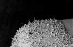
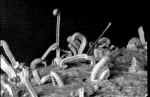
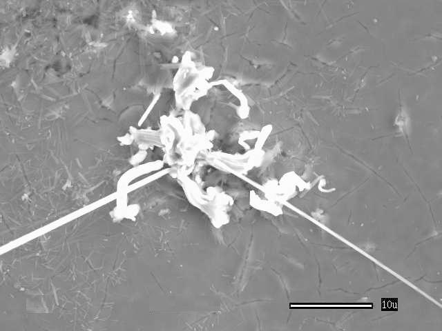
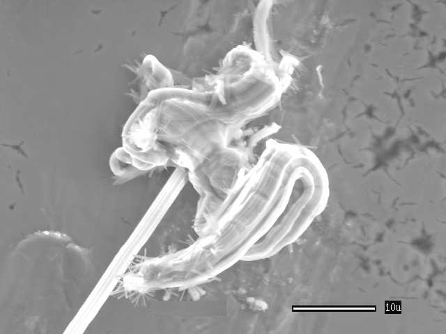
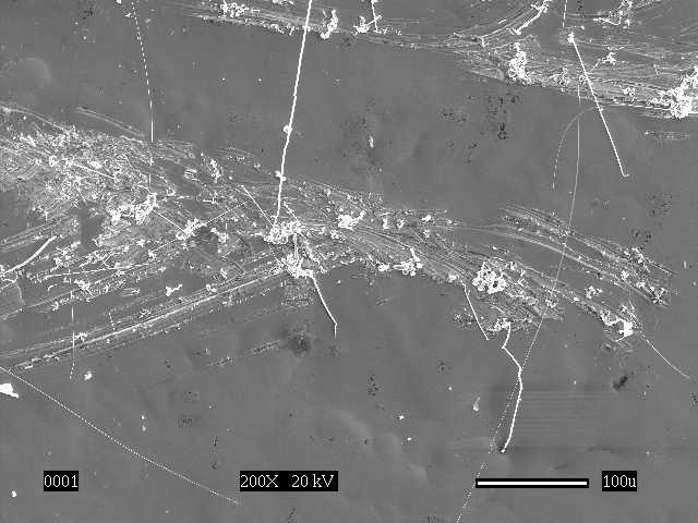
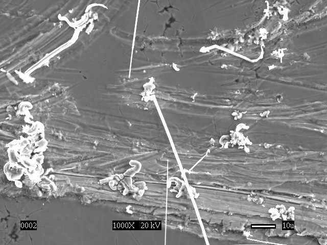
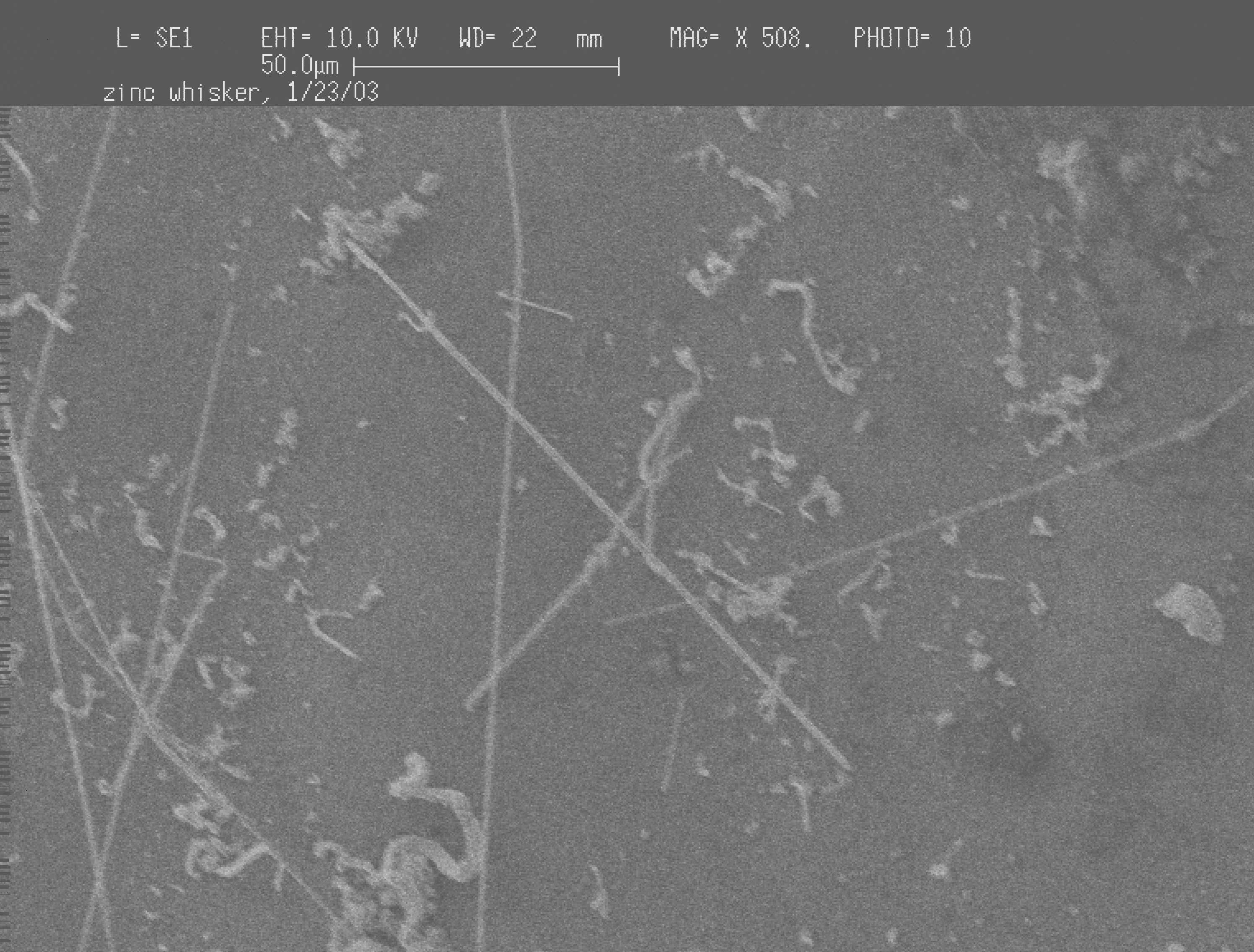
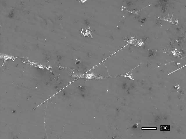
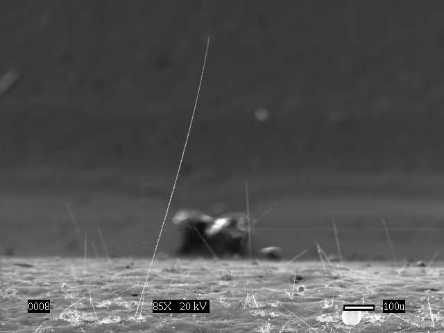
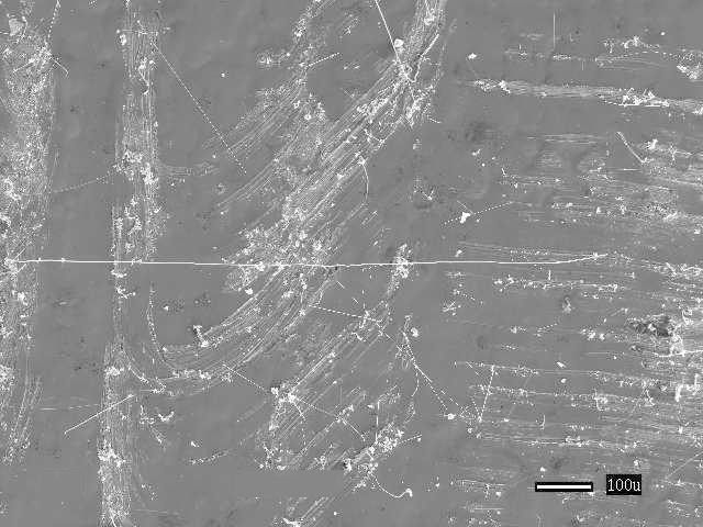
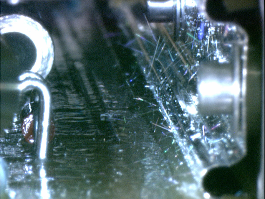
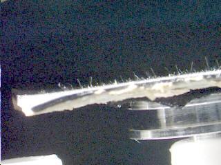
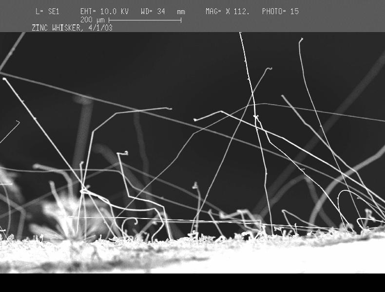
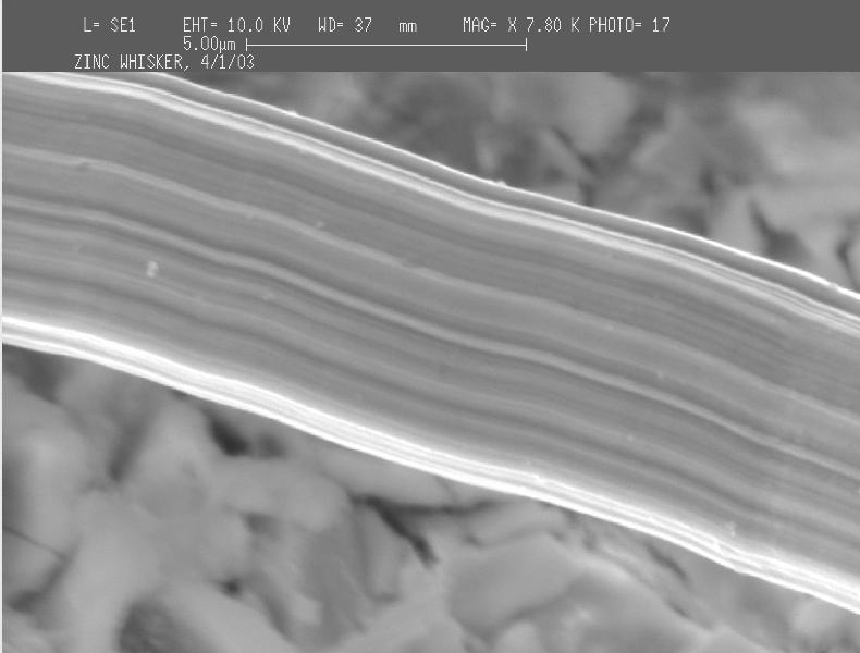
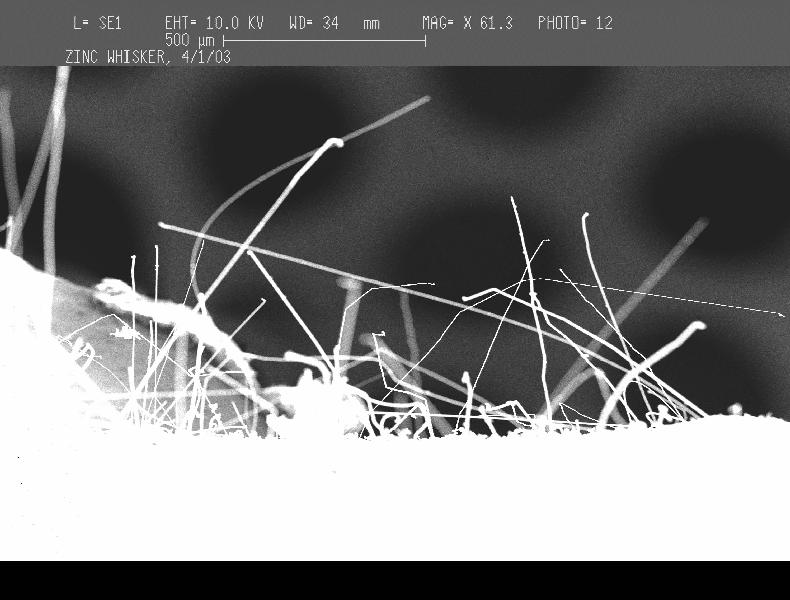
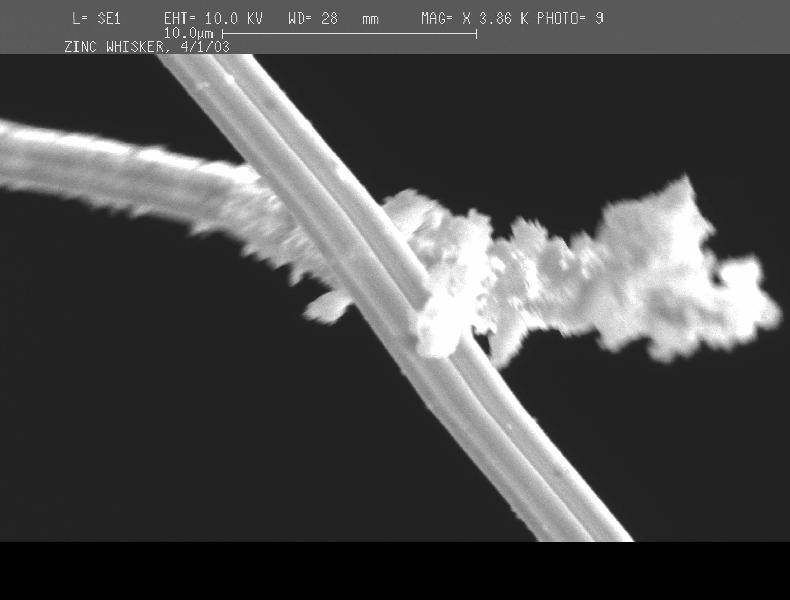
The whiskers below are ZINC
WHISKERS. They were found growing on the zinc-coated
steel underside of raised floor tiles. In these examples the floor
tiles were part of a computer room in which zinc whisker debris was shed
from the floor tiles especially during maintenance activities within the
data center . The conductive whisker debris was distributed around
the room via the air cooling system. Ultimately, some whisker debris
was drawn inside of the electronic systems (e.g., servers, routers, disk
arrays) operating in the data center resulting in catastrophic and/or
intermittent short circuit failures.
See the presentation: "Zinc
Whisker Awareness: Could Zinc Whiskers Be Impacting Your
Electronics?" for More about Zinc Whiskers
ADDITIONAL
GALLERY of Zinc Whisker Photos on Raised Floor Structures
|
Optical Image of Zinc Whisker on Floor Tile
|
SEM Image of Zinc Whiskers on Floor Tile
|

SEM Close-Up of Zinc Whiskers on Floor Tile
|
|
SEM Image of
Zinc Whiskers on Floor Tile
|

SEM Image of Zinc Whisker on Floor Tile
|
|
Images
Courtesy of NASA-GSFC
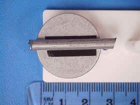
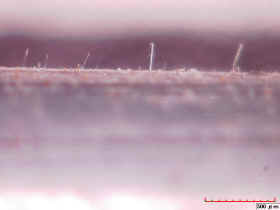
Hardware
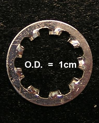
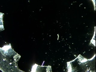
Lock Washer
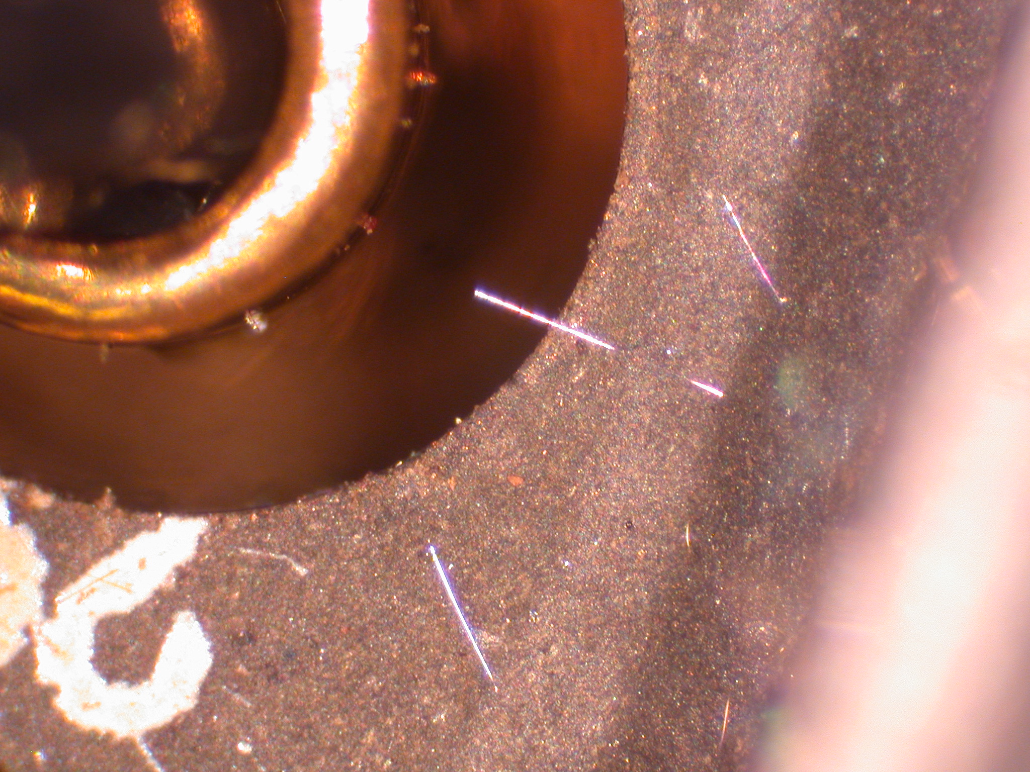
The following lock washer is tin-plated.
Finding tin whiskers on this washer requires patience and familiarity with
proper techniques to illuminate and inspect for metal whiskers.
See
Video of this Lock Washer demonstrating how difficult it can be to inspect
for tin whiskers using optical methods
Images
Courtesy of NASA-GSFC
Pipe/Conduit
Steel Pipe, Zinc-Coated by
Process of Hot Dip Galvanized (HDG)
This steel pipe was zinc-coated using a "hot dip galvanization"
(HDG) process (i.e., immersed into molten zinc). Despite frequent claims
to the contrary, HDG coatings are NOT immune to the formation of zinc
whiskers as this specimen clearly shows. The pipe had been kept in a
warehouse storage for ~15 years prior to discovery of the whiskers.
Whiskers in excess of 10 millimeters have formed on this specimen.
Additional
Photos and Measurements of this Zinc Whisker Infested Pipe
(Courtesy of Lyudmyla Panashchenko)
Video
of This Pipe Demonstrating How Whiskers Flex in the Presence of Electric
Fields
Pipe sample donated to NASA Goddard by
Reima Lahtinen
Optical photos courtesy of NASA-GSFC
SEM photos courtesy of Lyudmyla Panashchenko
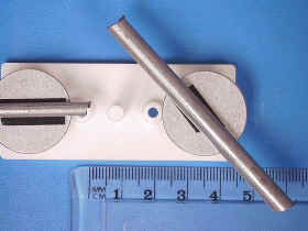
Terminal
Lugs
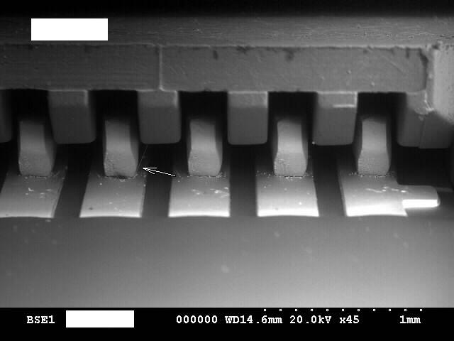
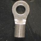
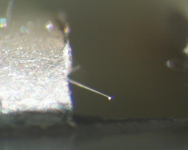
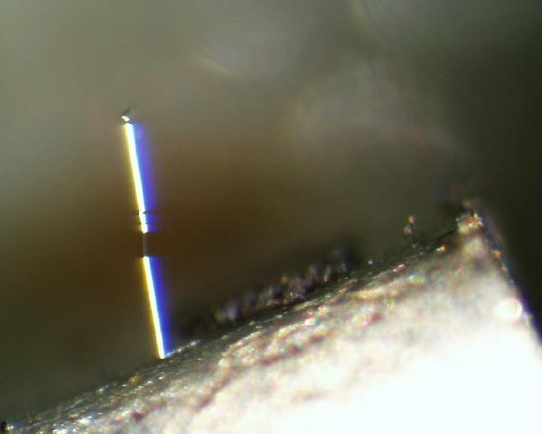
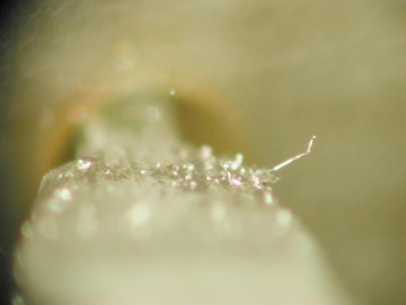
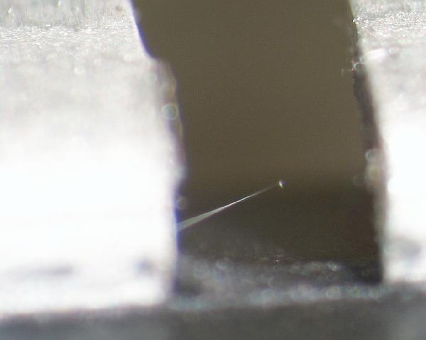
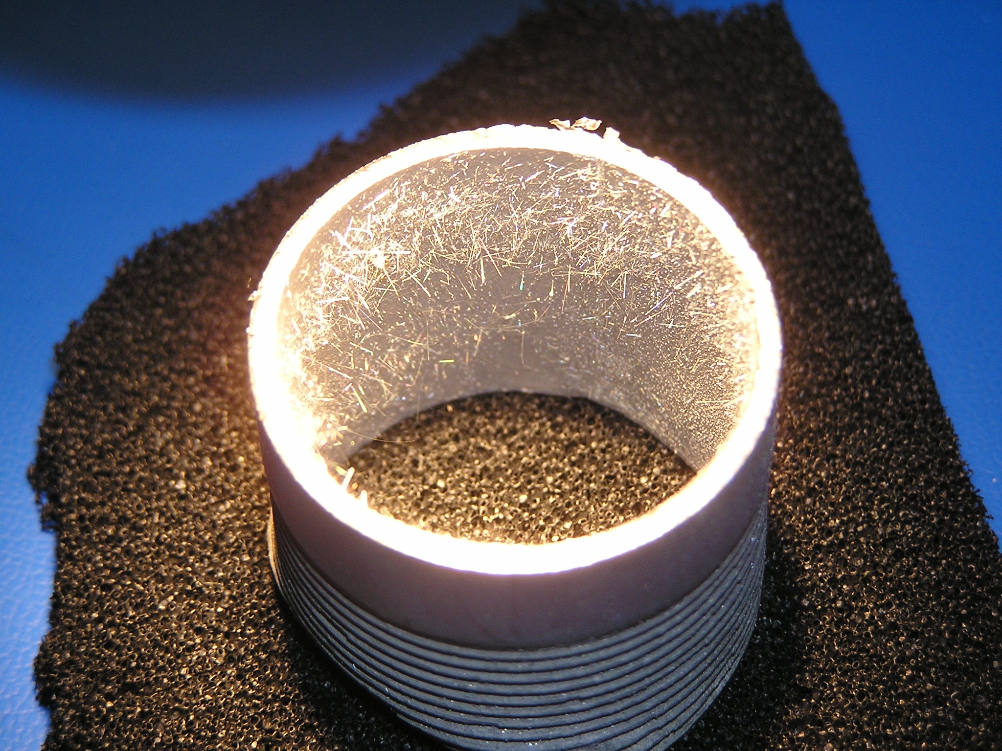
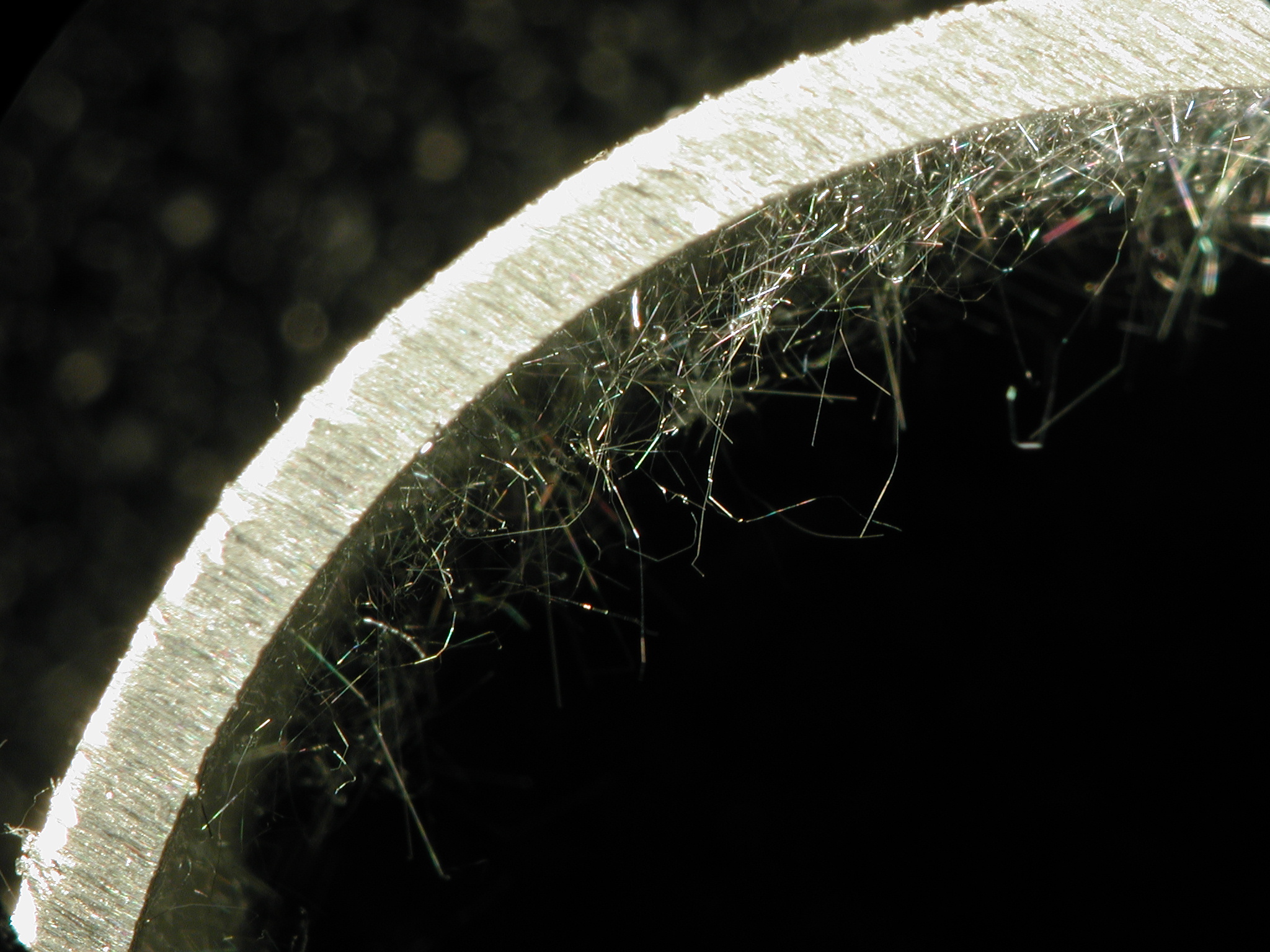
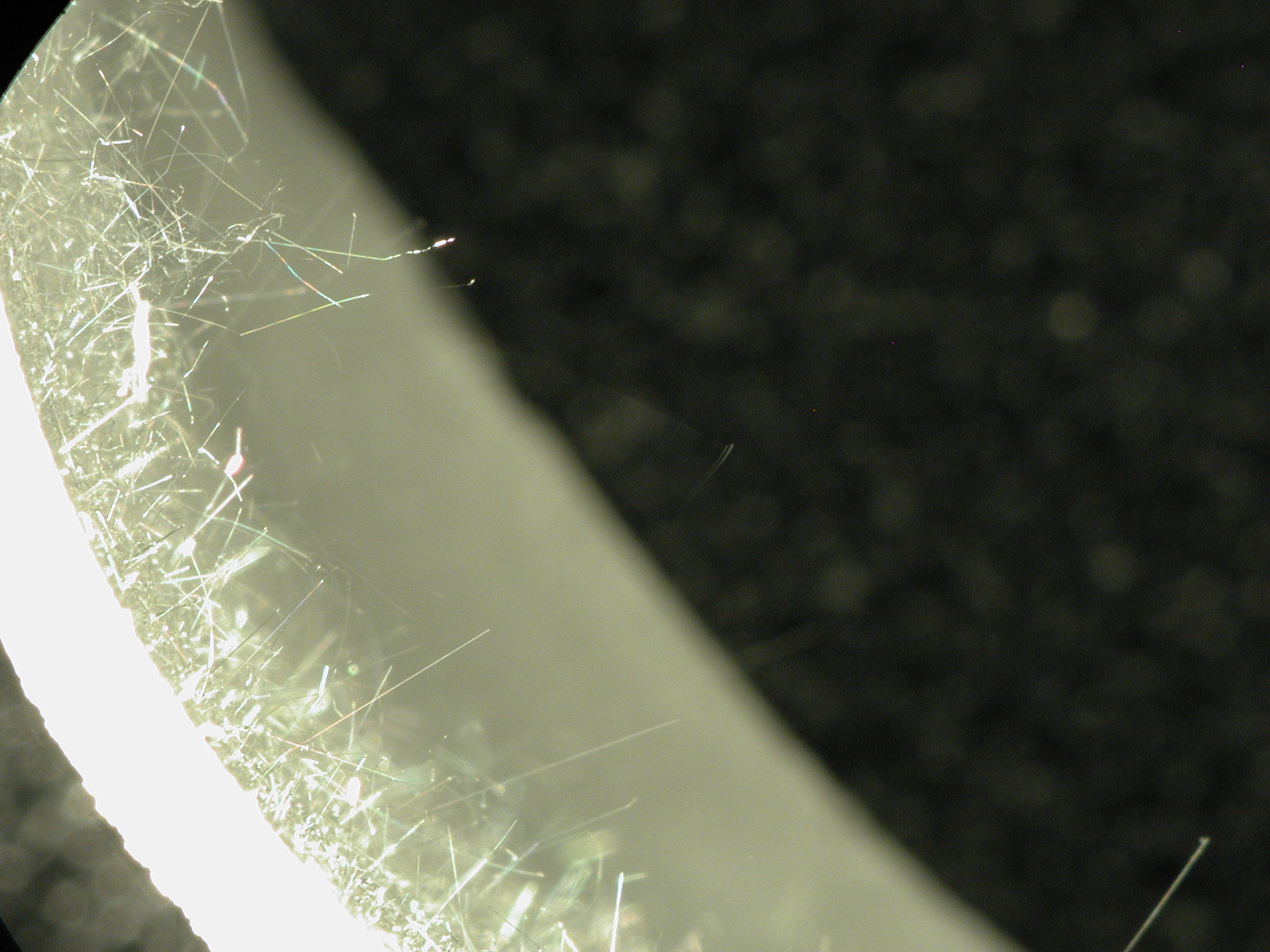
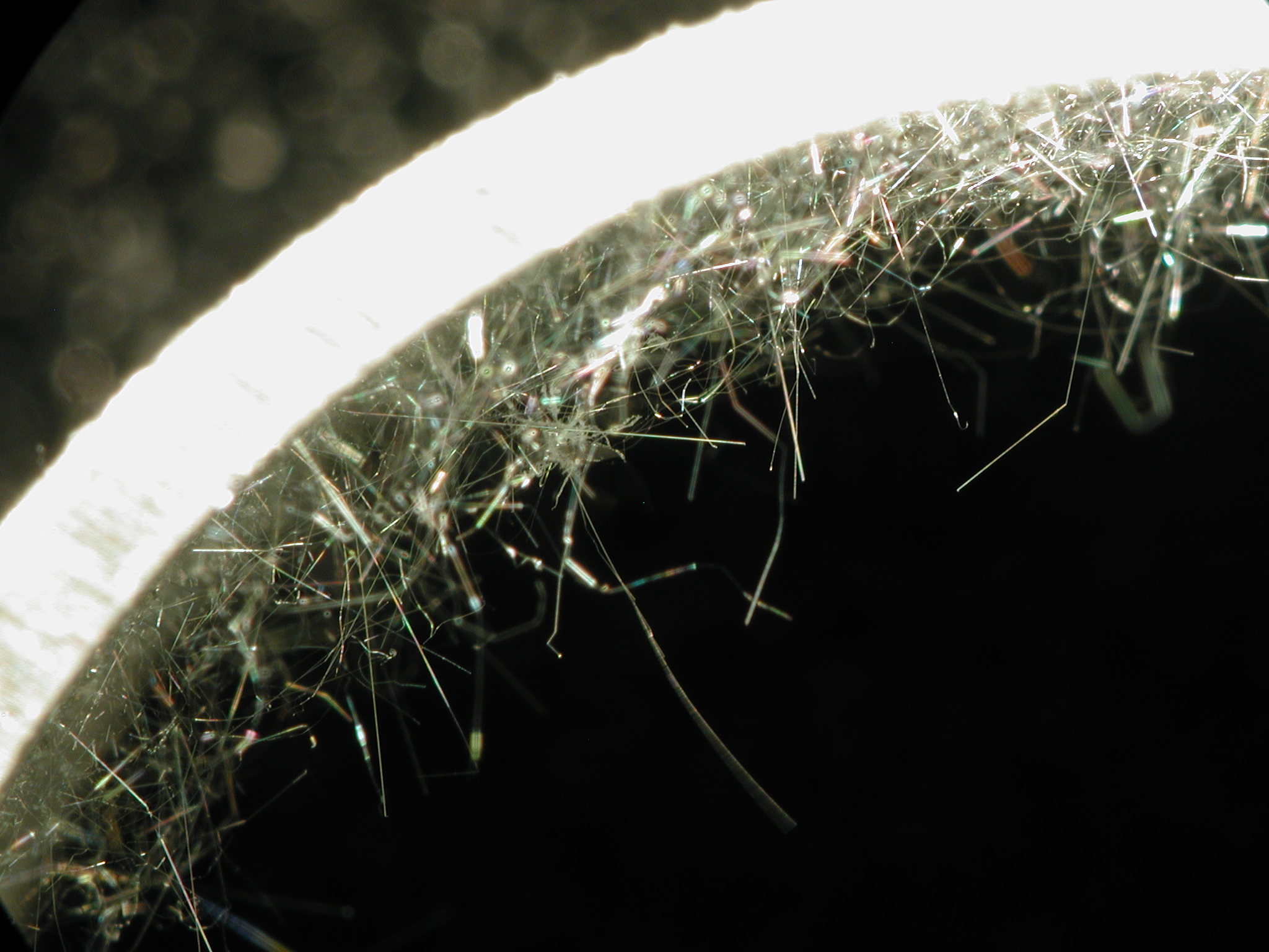
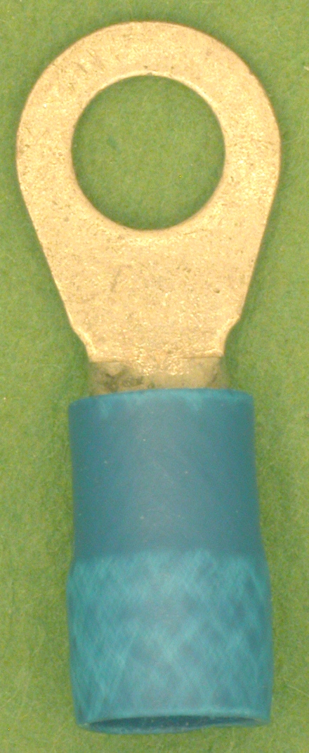
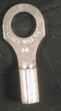
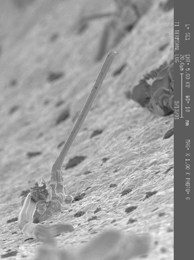
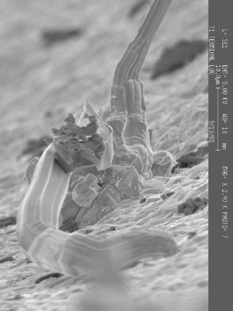
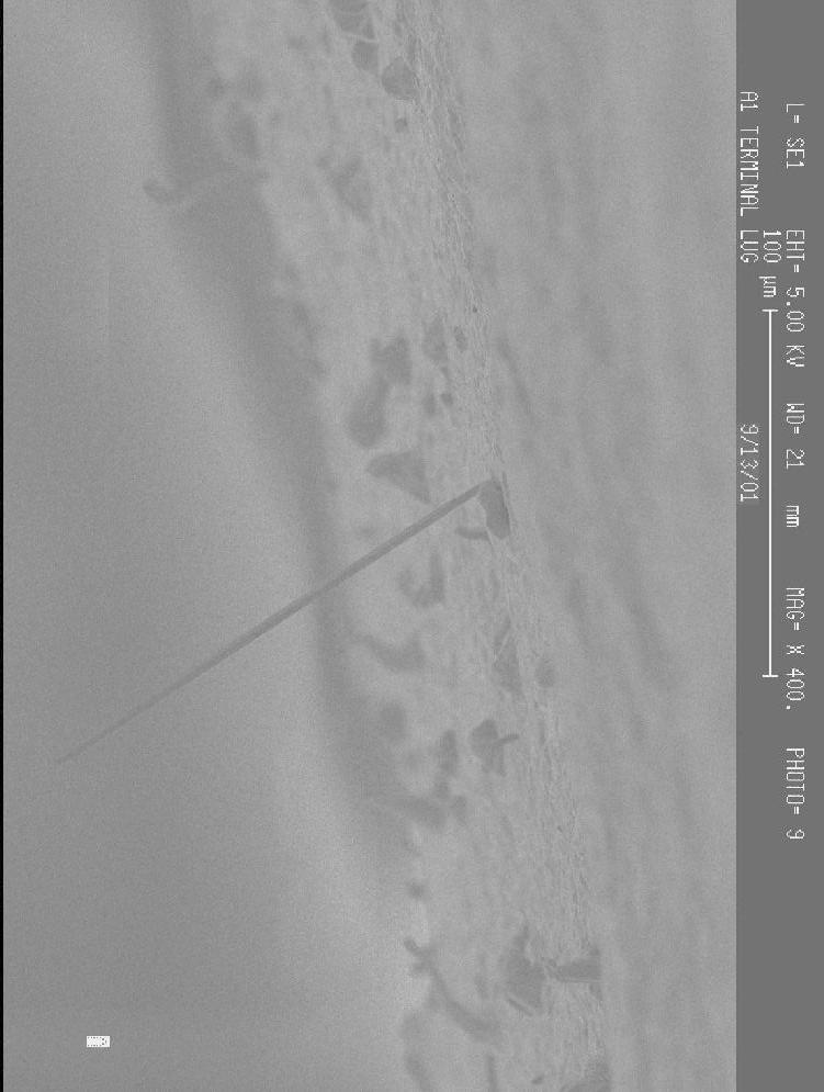
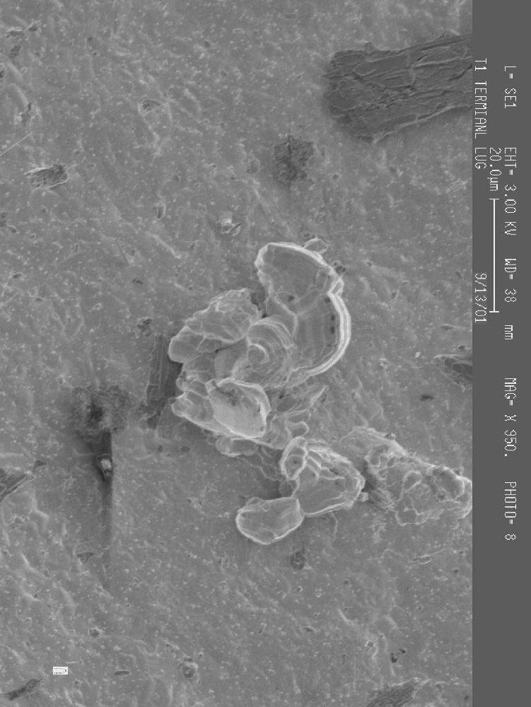
Terminal Lugs, Ring Type,
Tin-Plated
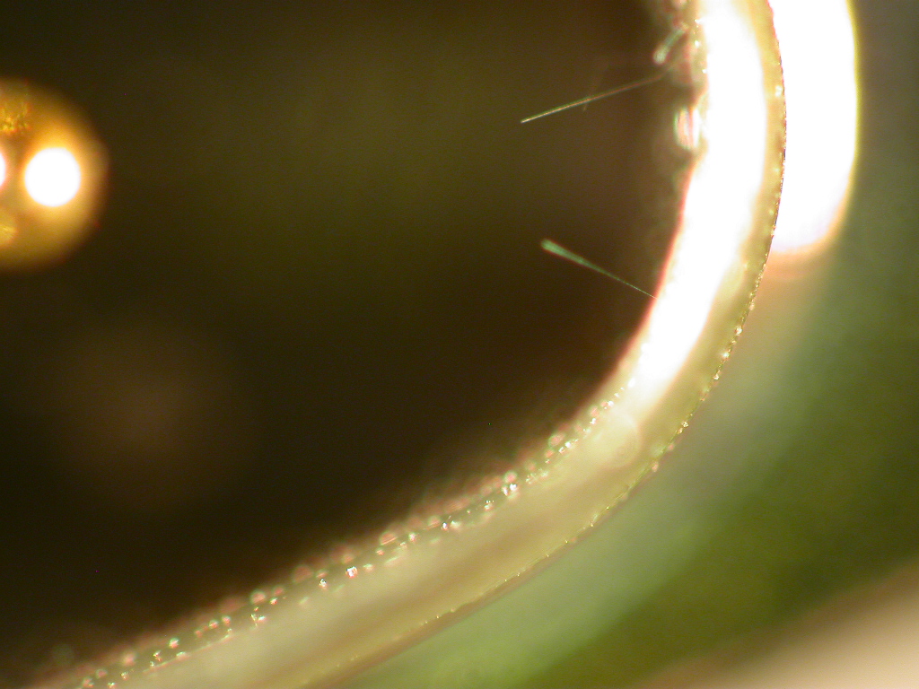
The terminal rings shown below are plated
with pure tin. These terminal rings are commonly used in
"crimp" type applications where a stranded wire is inserted into
the barrel and crimped in place. The ring terminal portion is most
often mounted using a nut and bolt to adhere the ring to a conductive
surface such as a chassis. Other terminal types shown include fast-on
(spade) terminals.
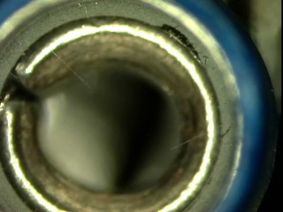
These photos are of "unused/loose
piece" terminal rings taken straight from the manufacturer's shipping
containers. In many cases the whiskers are found "inside" the crimp barrel of these
parts which is protected from abrasion that can dislodge whiskers from
the exposed surfaces.
See
a Video of Tin Whiskers found Inside the Crimp Barrel of One of the
Terminal Lugs shown below
Images
Courtesy of NASA-GSFC
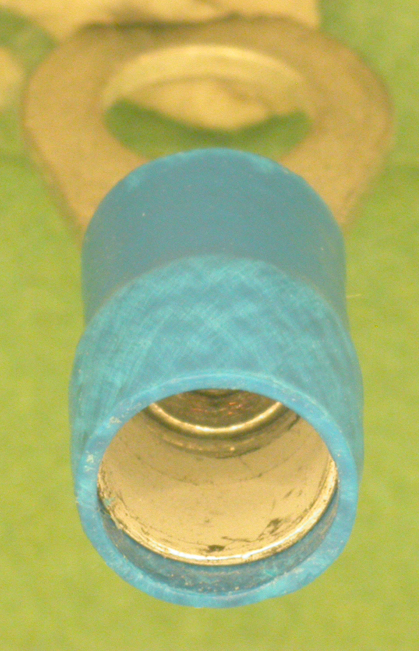
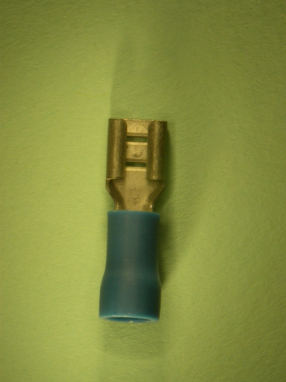
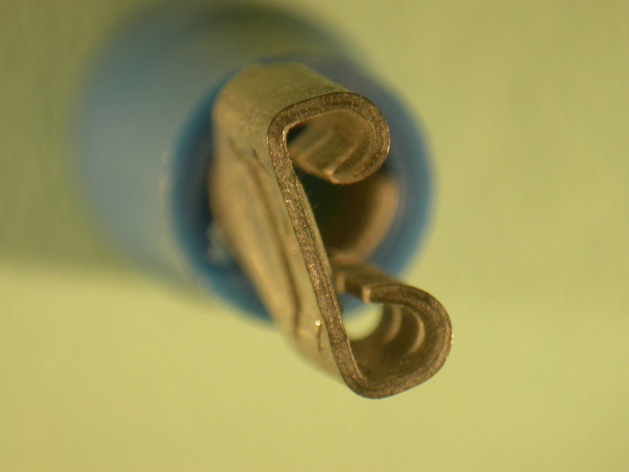
Terminal Lugs, Spade Type,
Tin-Plated
Images
Courtesy of NASA-GSFC
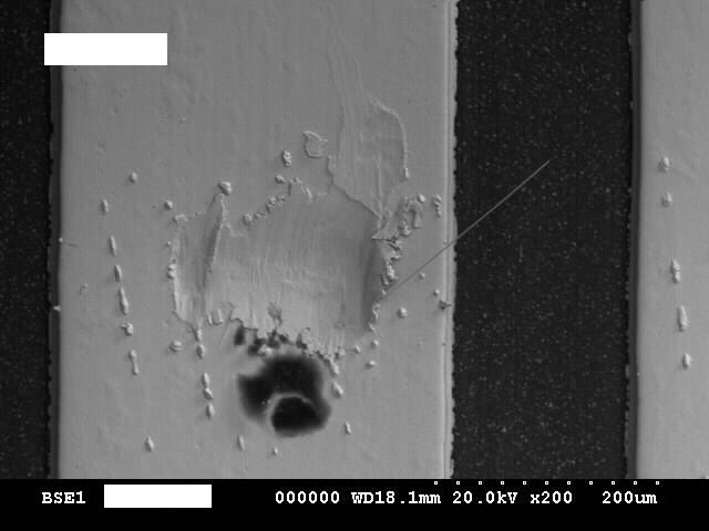
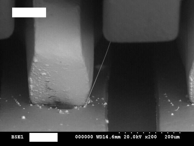
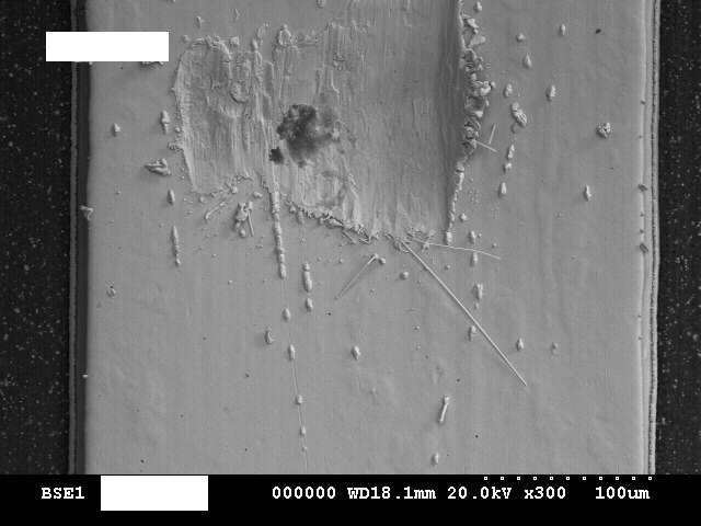
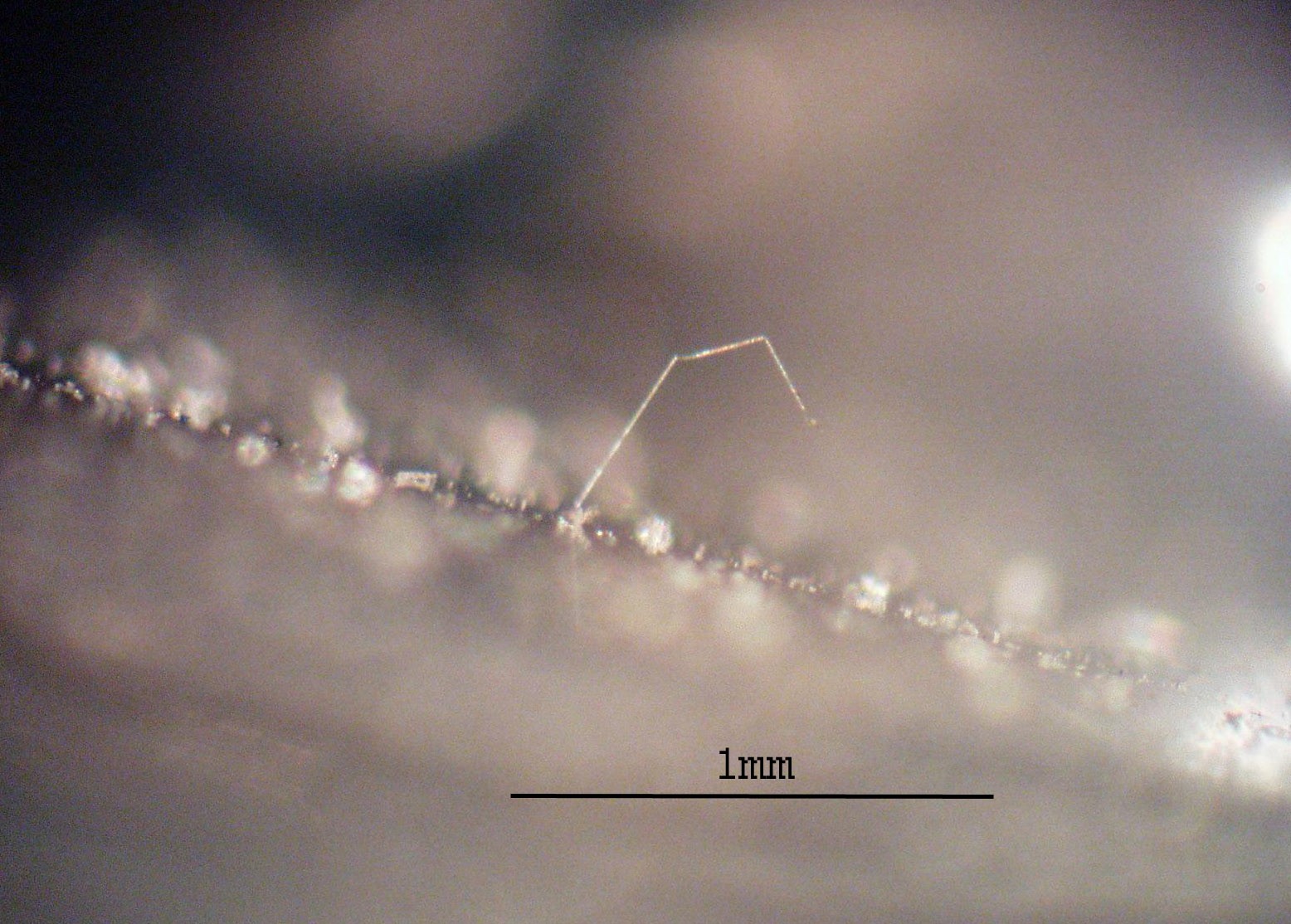
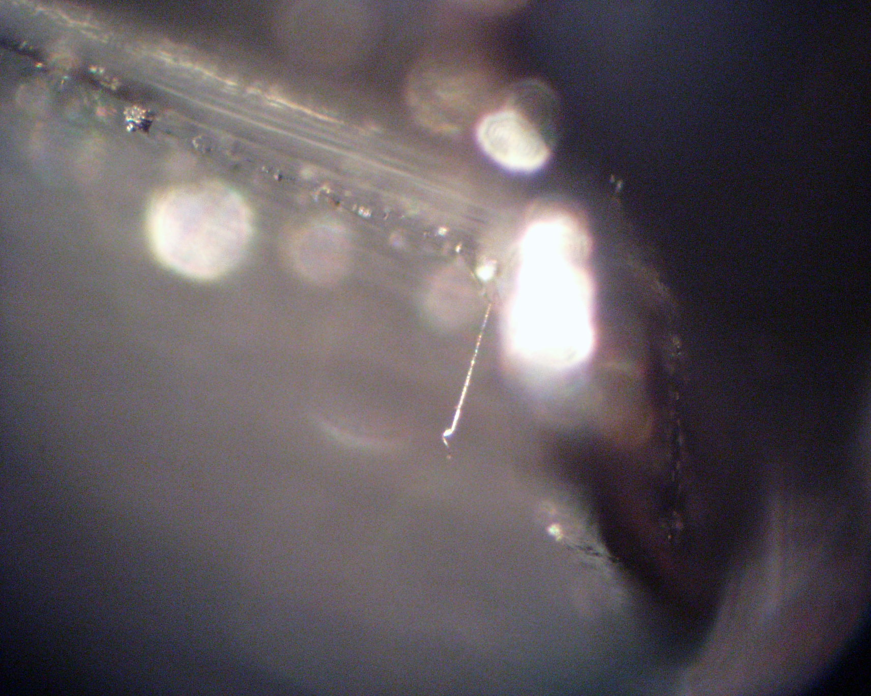
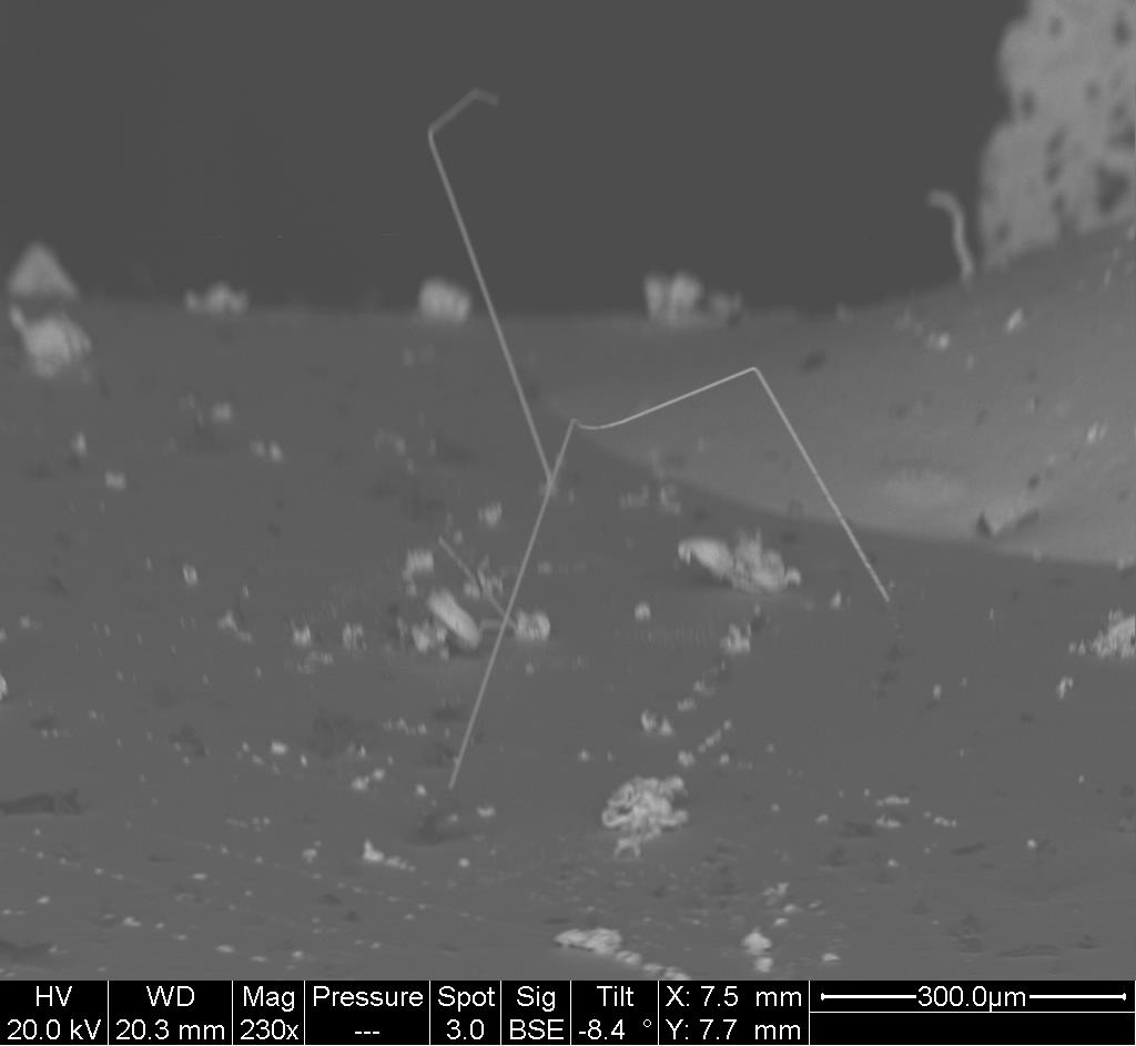
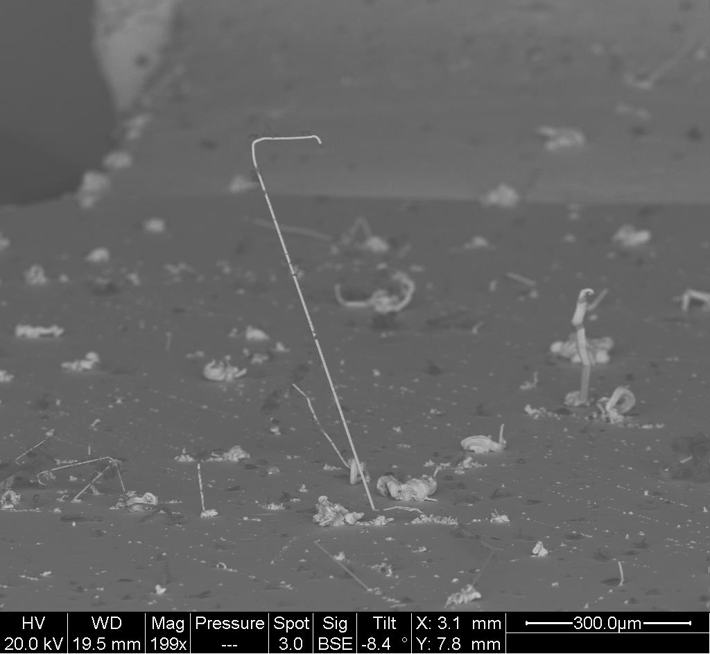
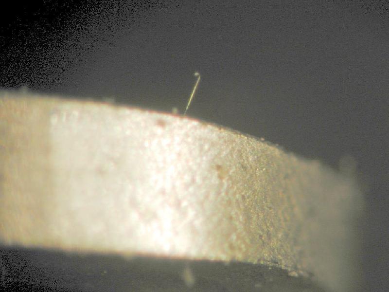
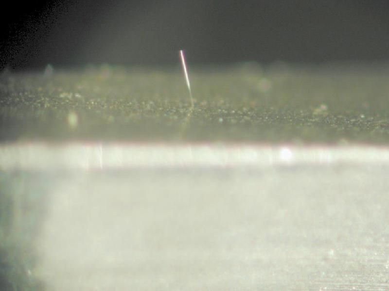
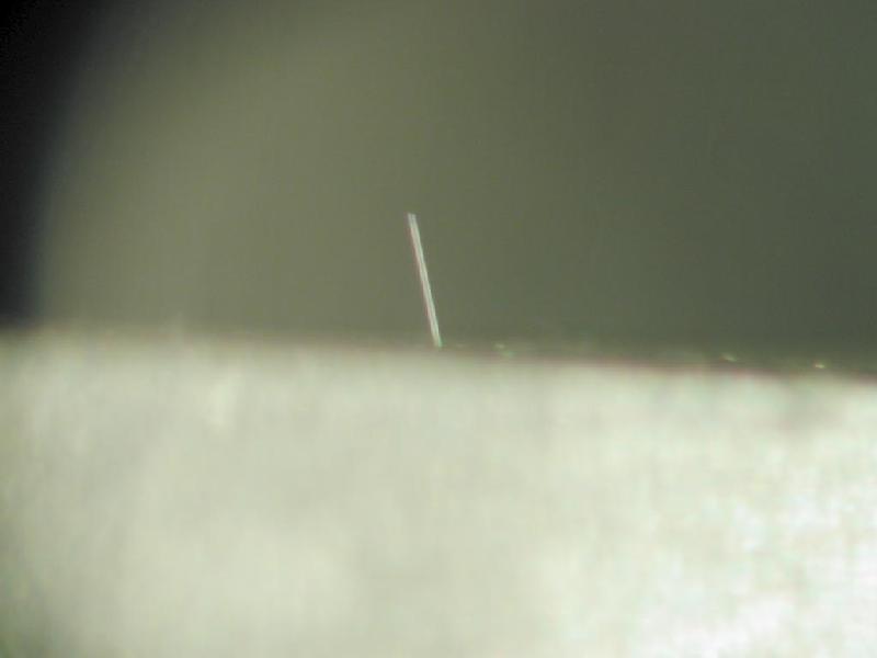
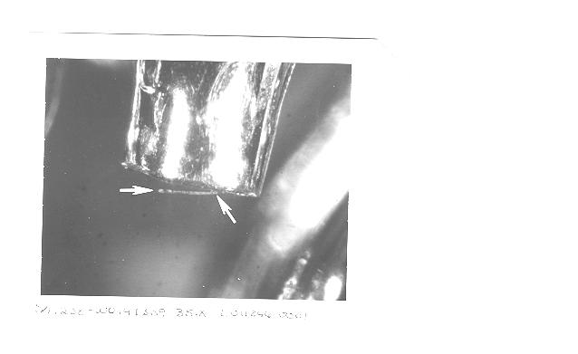
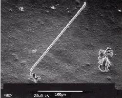
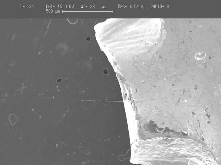
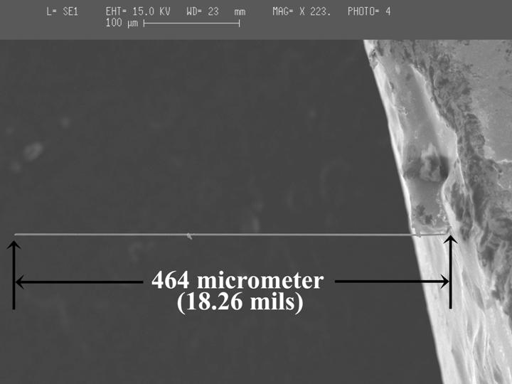
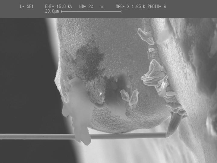
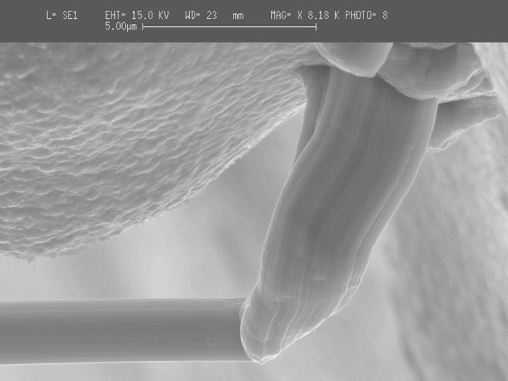
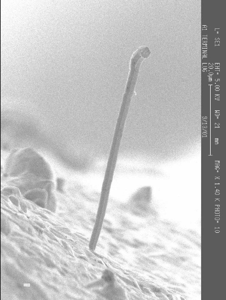
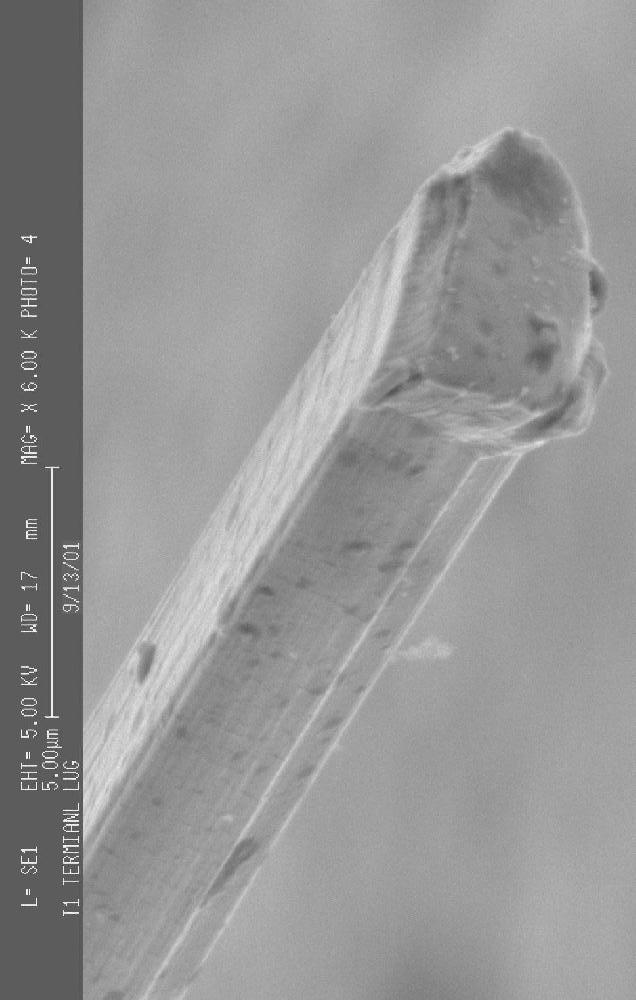
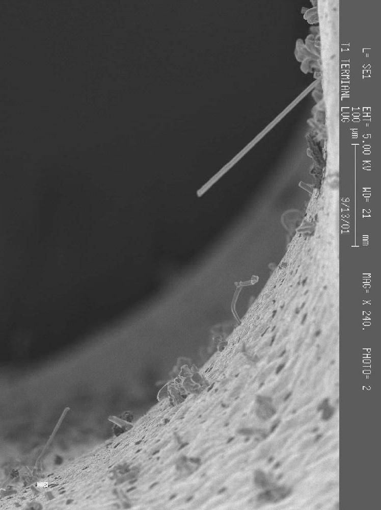
Terminal Lugs, Tin-Plated,
Manufacturer "A"
Overall View of Tin-Plated Terminal Lug--Vendor A |

Tin
Whisker Inside Crimp Barrel--As-Received |

Close-up of Tip of Whisker |
Images
Courtesy of NASA-GSFC
Terminal Lug, Tin-Plated,
Manufacturer "B"
Images
Courtesy of NASA-GSFC
Test Points
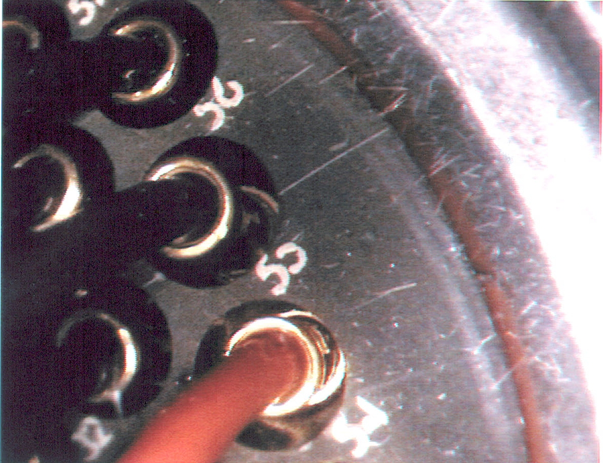
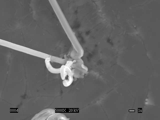
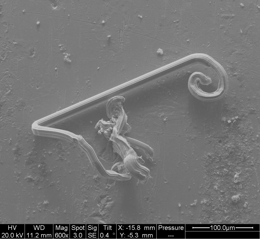
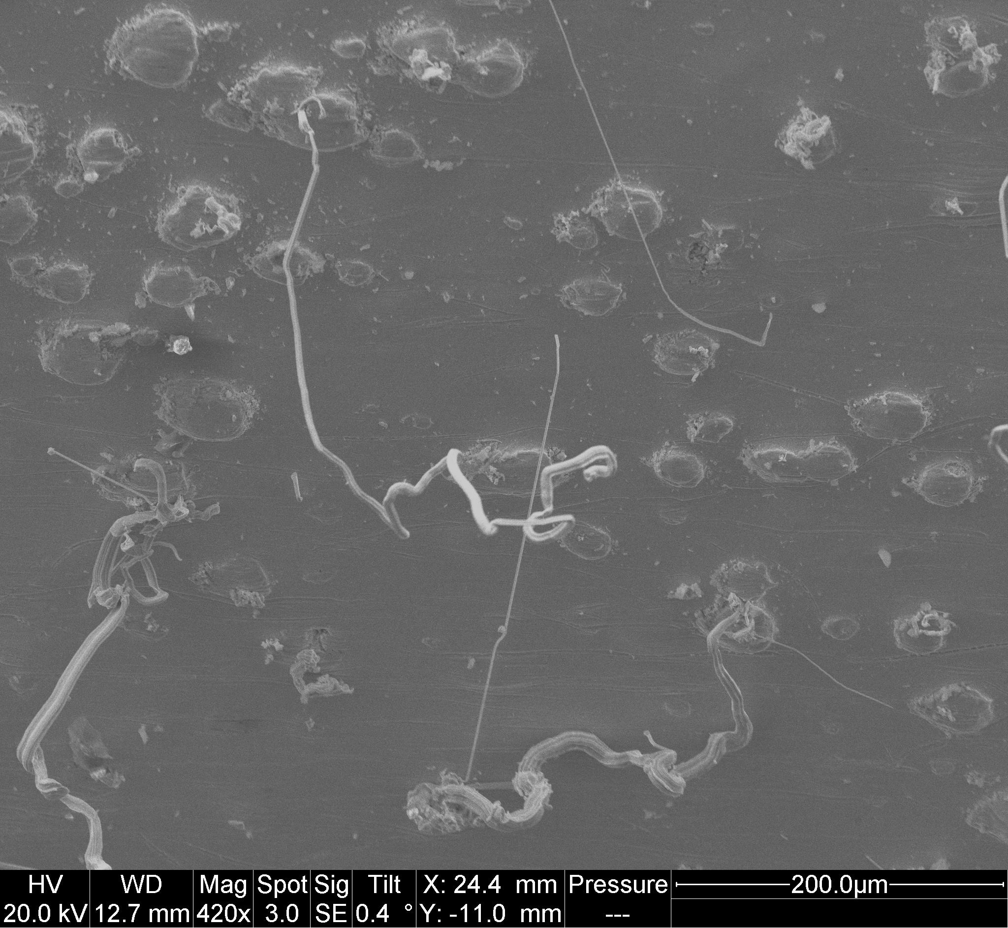
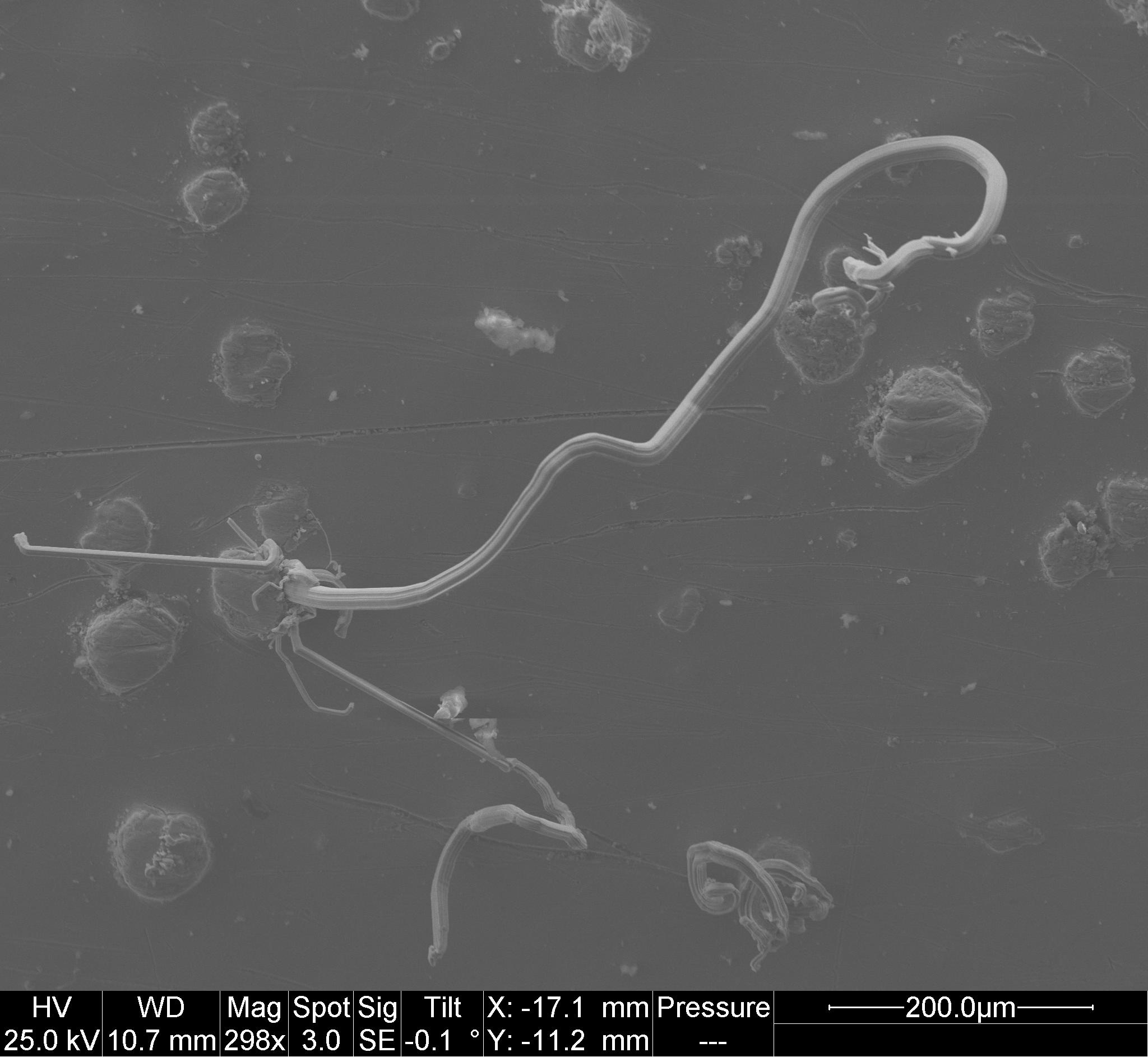
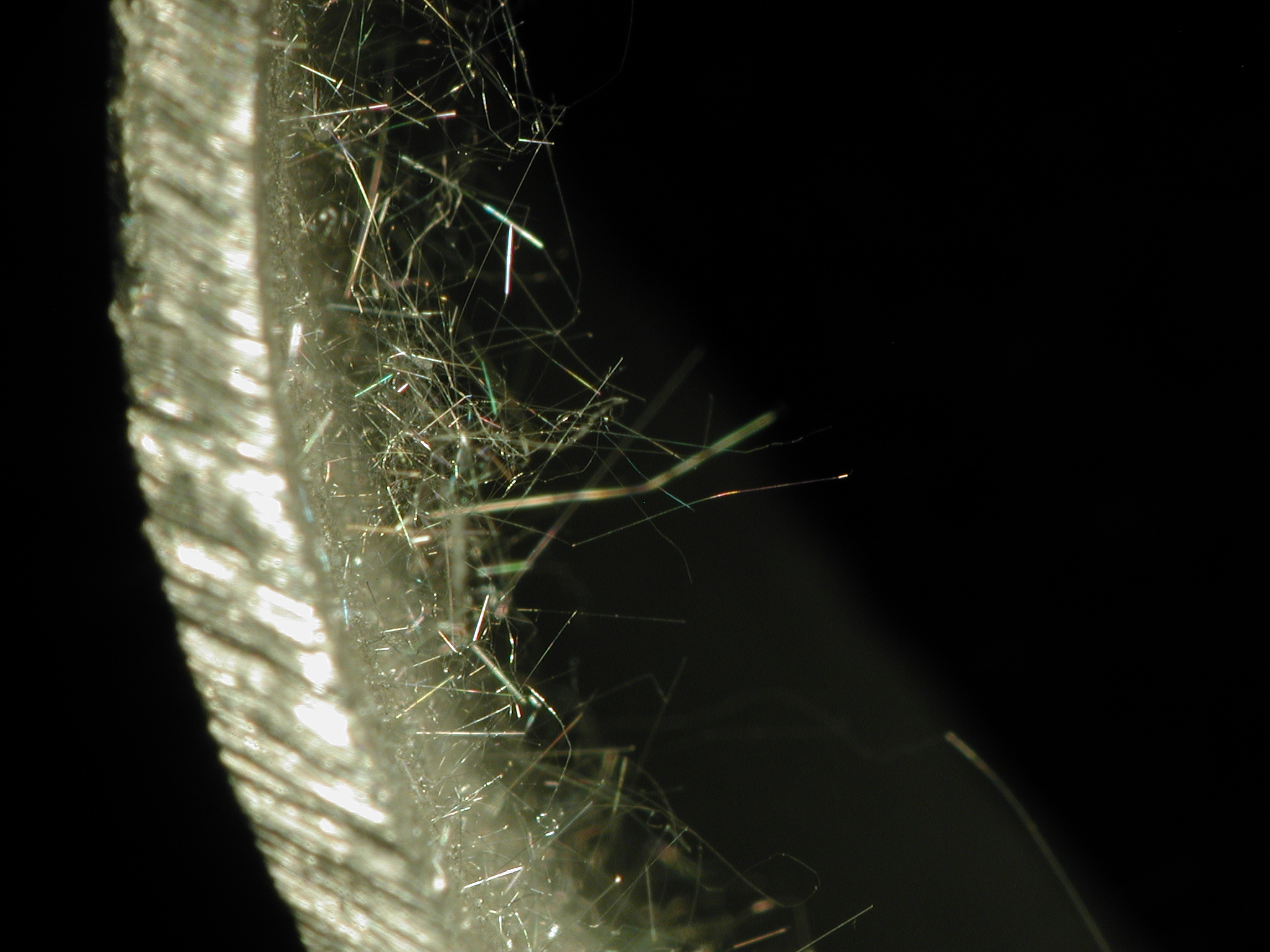
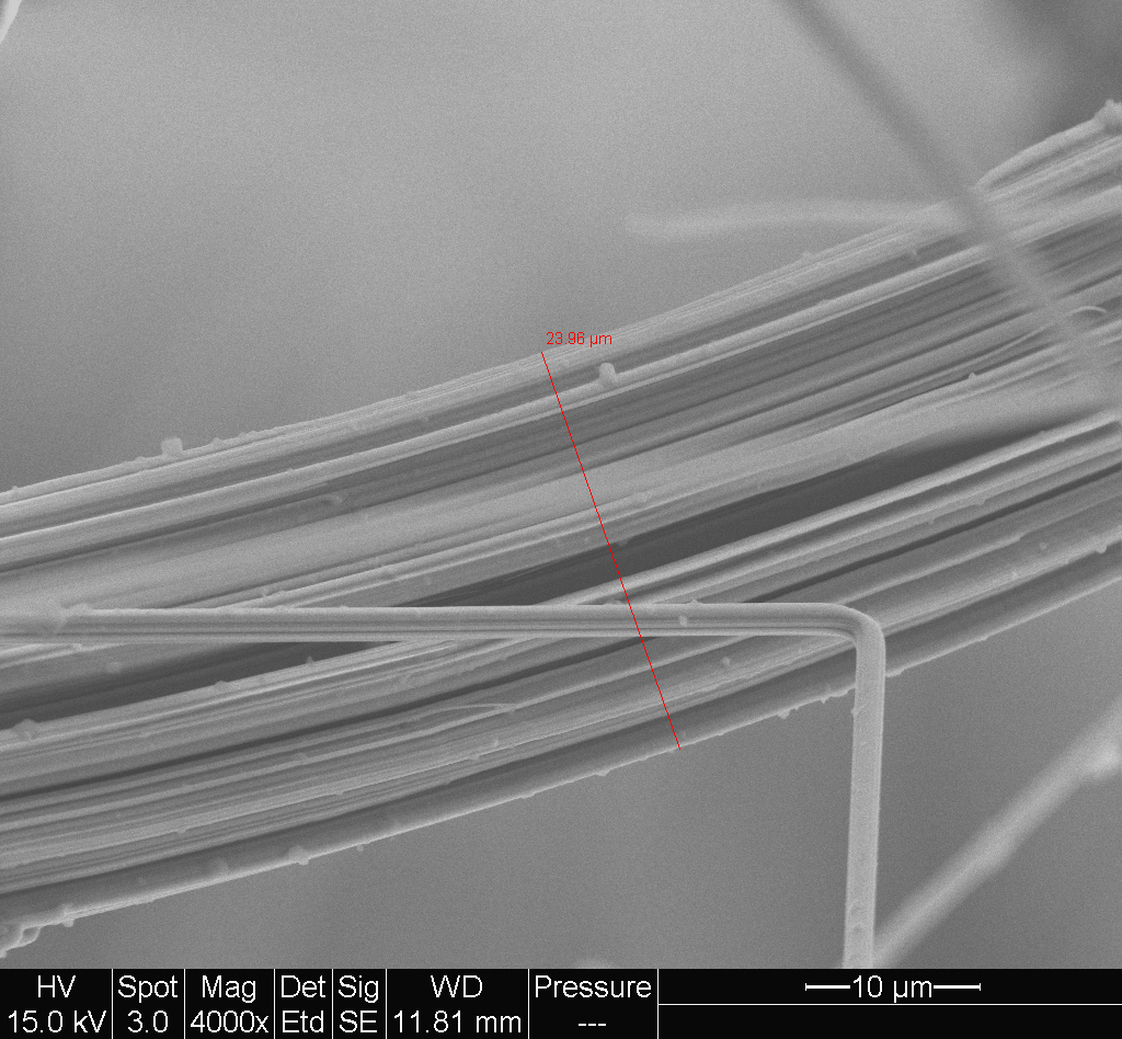
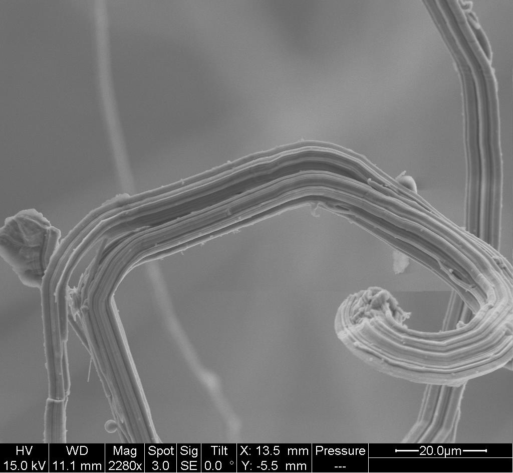
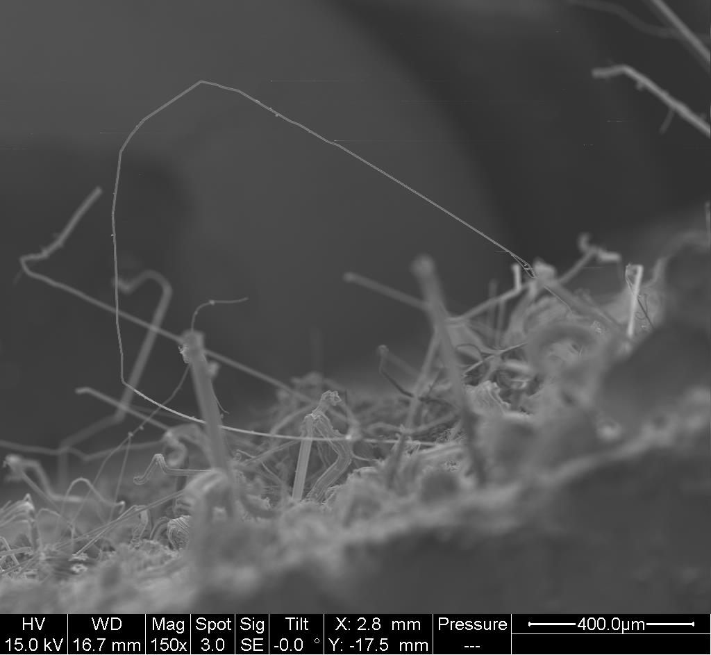
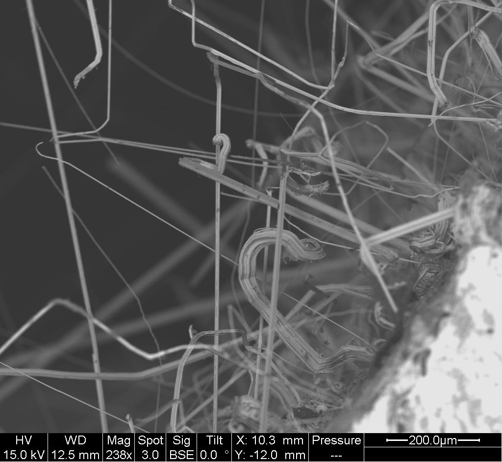
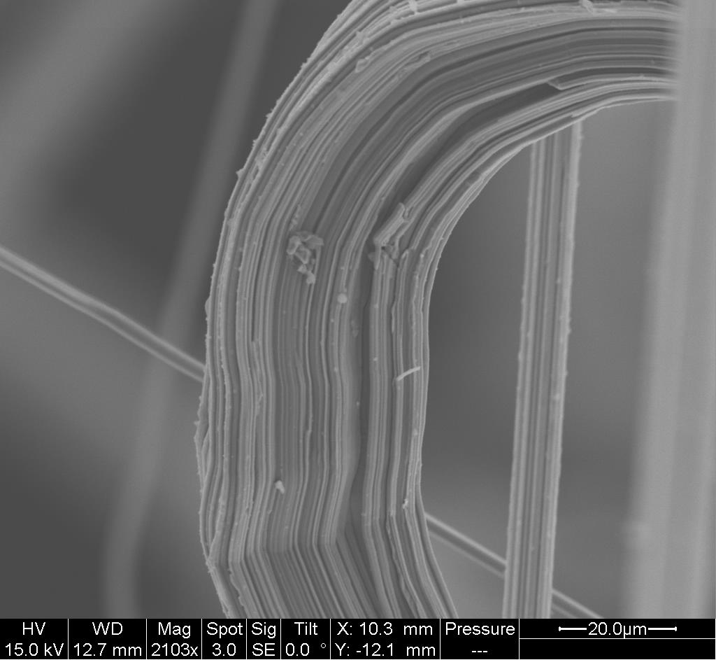
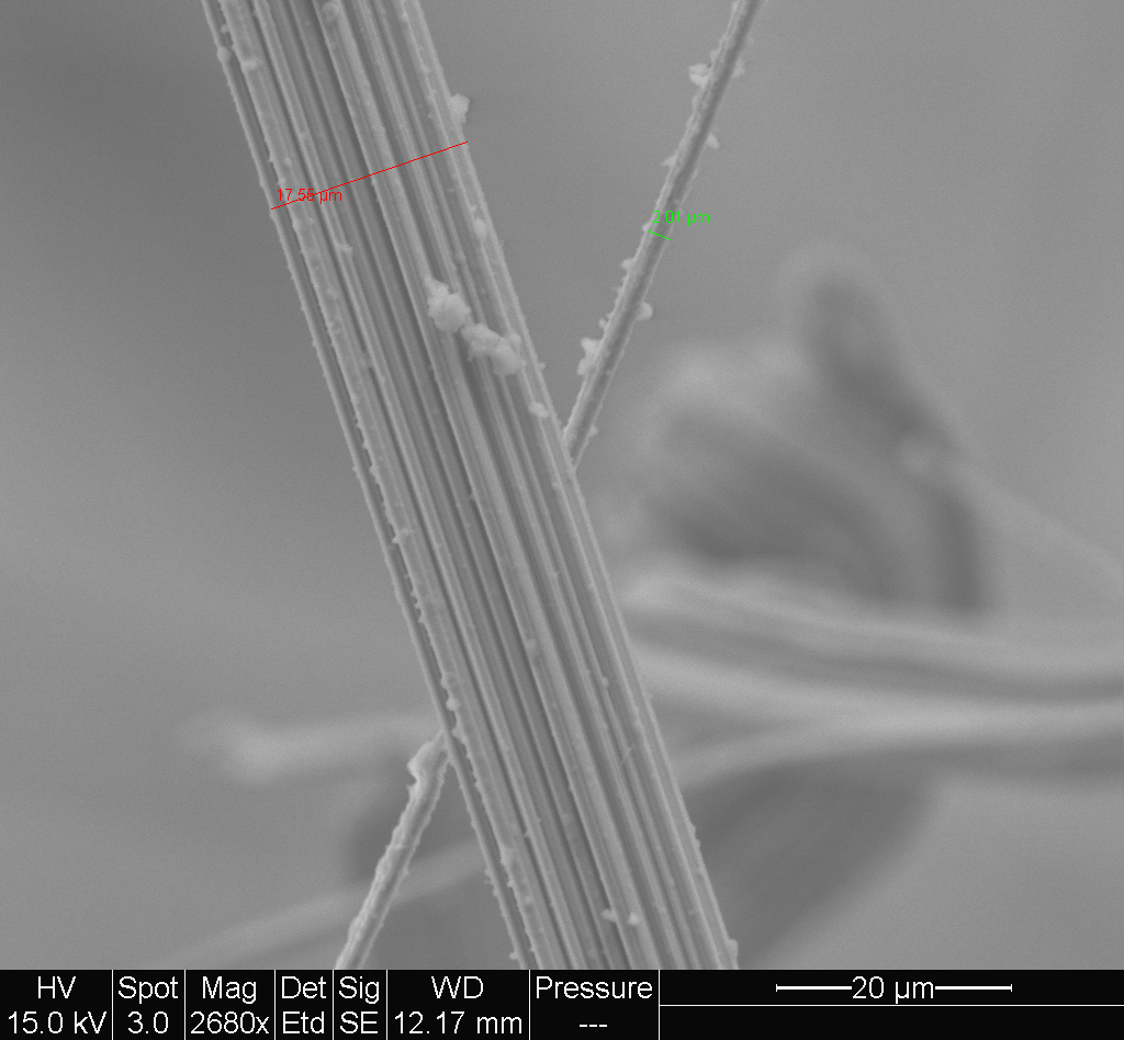
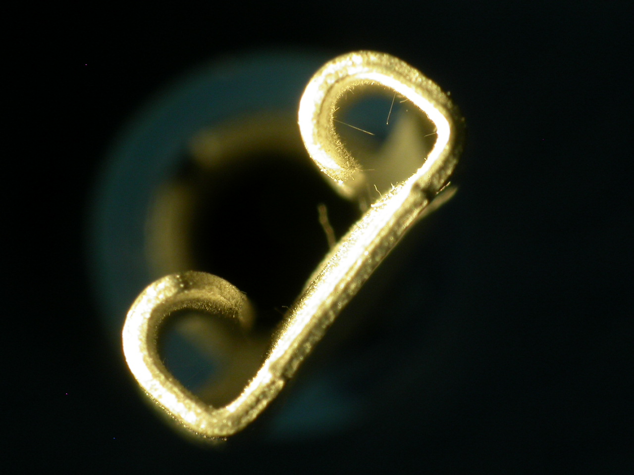
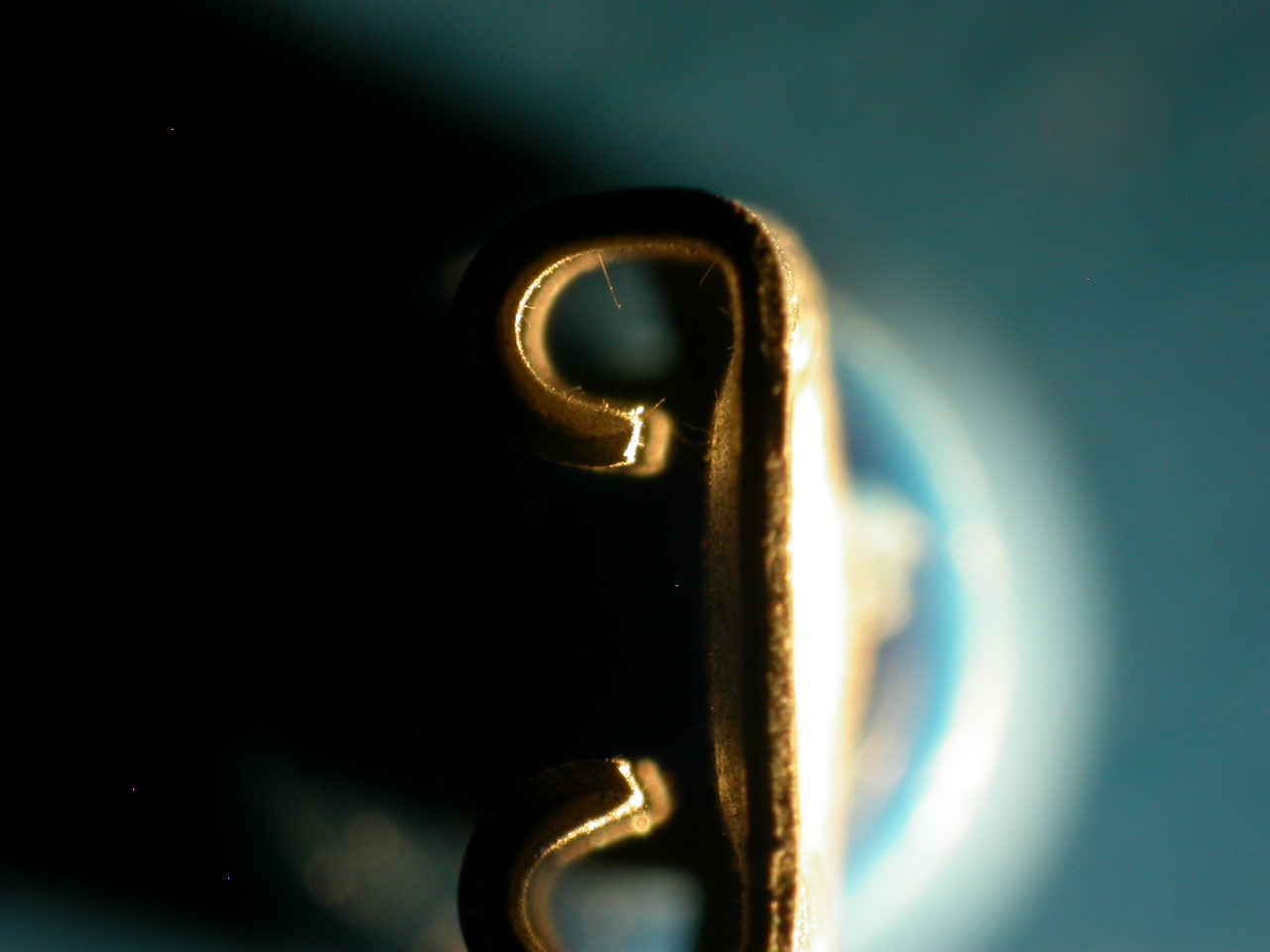
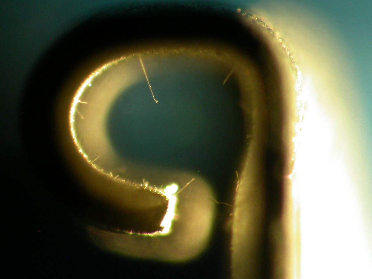
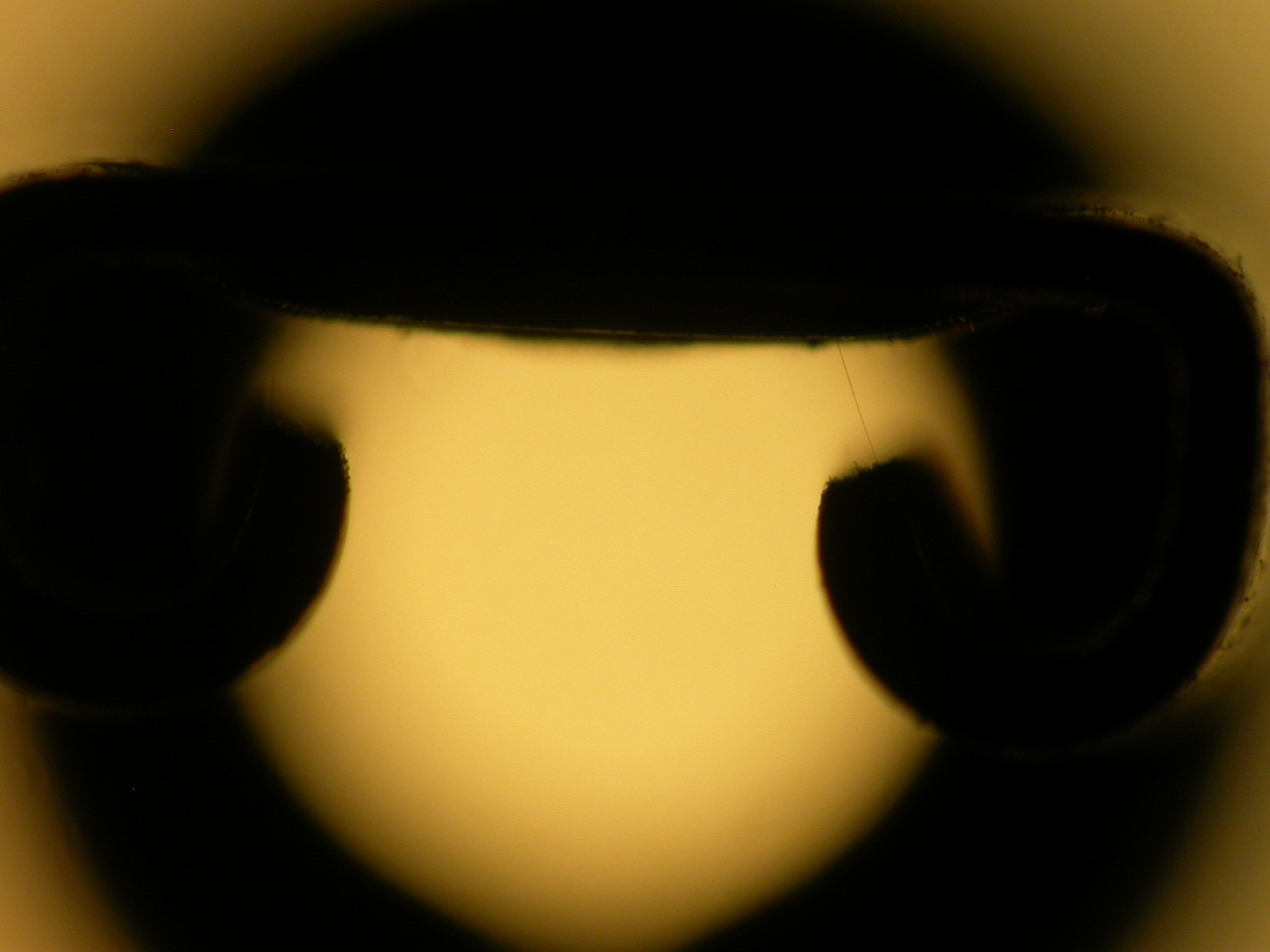
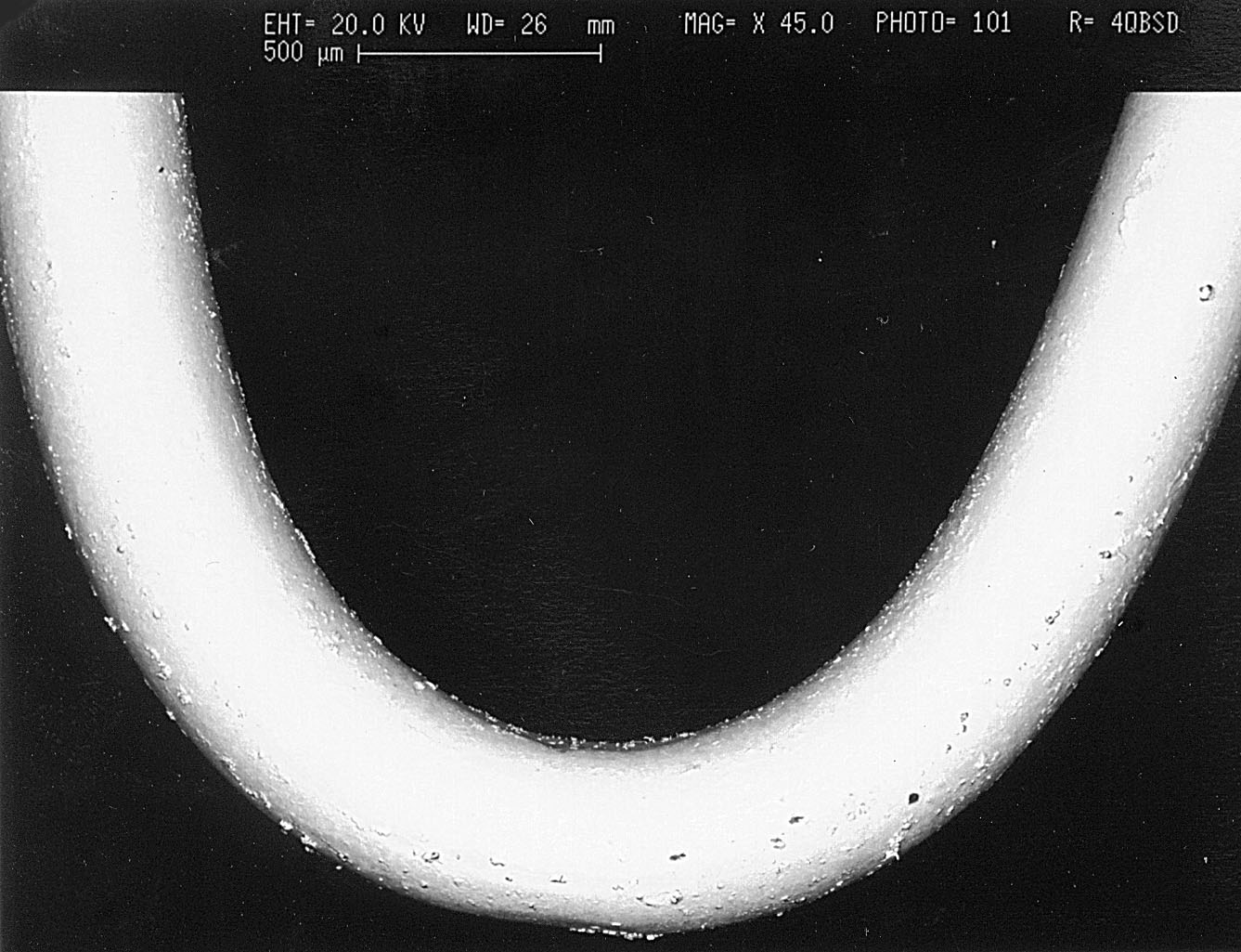
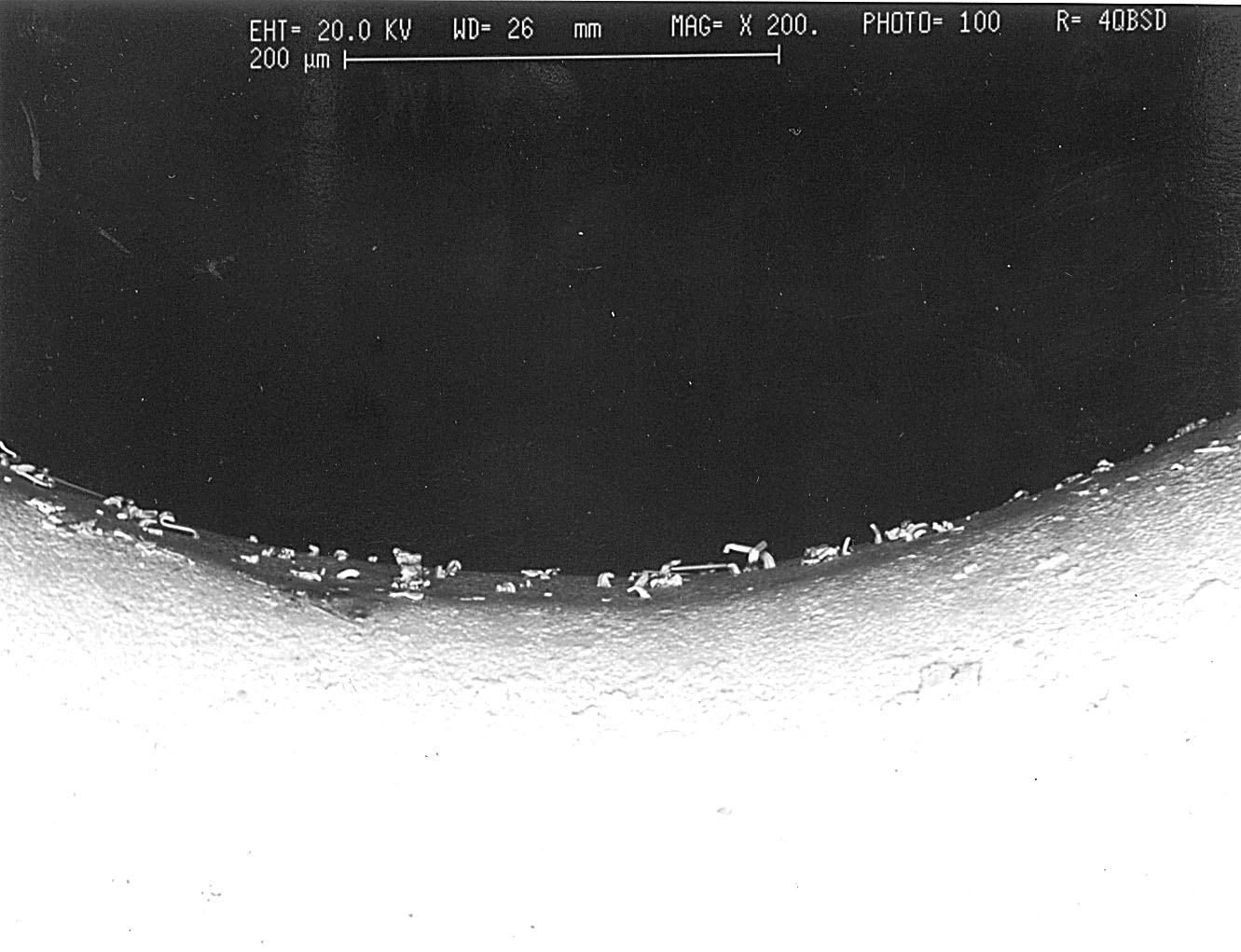
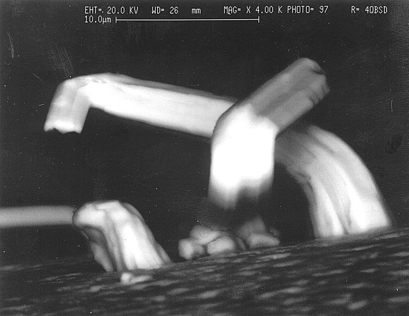
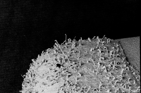
Test Points, Tin-Plated
The test points shown here are "bright"
tin-plated phosphor bronze loops. They are commonly installed on PC
Boards as access points for attaching test leads/probes to monitor signals
and voltages during board level testing.
|
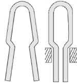
Overall Diagram of Test Point
|
Wide View of the Loop
|

Close-Up of Bend in Loop. Tin Whiskers are apparent
|
|
More Tin Whiskers on Test Loop
|
More Tin Whiskers on Test Loop
|

Detailed View of Tin Whiskers on Test Loop
|
|


