|
Experiment
#5: Last Updated October 2002 - Continued Monitoring Planned
Tin Whiskers Growing from the Terminations of Pure Tin
Plated Ceramic Chip Capacitors After Temp Cycle Followed By Ambient
Storage
|
|
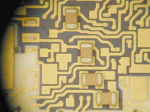
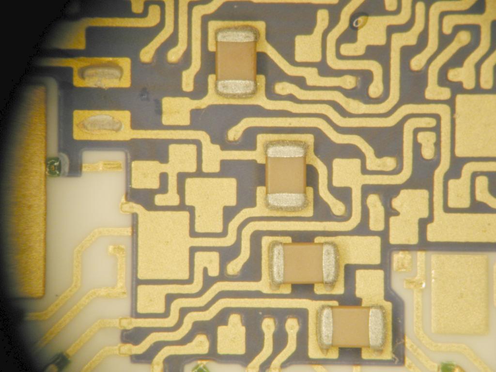
Inside of a Hybrid Microcircuit Package
with Pure Tin-Plated Ceramic Chip Capacitors
Mounted by Conductive (Silver) Epoxy
|

Tin Whisker Growth on Capacitor Terminations
after 200+ Temp Cycles
From -40°C to +90°C Followed by Months of Ambient Storage
(2002-Oct)
|
Purpose
Background
Interim Observations
Prior Research

Purpose:
This
experiment documents and monitors tin whisker growth on one lot of pure tin-plated multilayer ceramic capacitors
(MLCCs) mounted inside a hybrid using conductive (silver) epoxy and then
subjected to extensive thermal cycling followed by long term ambient
storage. The experiment was initiated in 2001 by a non-NASA entity
who then donated one of their test samples to NASA Goddard tin whisker
researchers for continued monitoring. Details of this study and
interim observations were formally published in June 2002 at the American
Electroplaters and Surface Finishers (AESF)
SUR/FIN conference in Chicago, IL. The paper also discusses similar
but unrelated experiments by others attempting to induce whisker growth on
tin-plated MLCCs.
- J. Brusse, "Tin Whisker Observations on
Pure Tin Plated Ceramic Chip Capacitors", AESF SUR/FIN
Conference, June 2002, pp 45-61
- Slide
presentation is also available.
The NASA Goddard
Whisker WWW Site will be used to provide updates as monitoring of these
specimens continues.
Background:
In 2001 a hybrid
microcircuit manufacturer informed NASA Goddard tin whisker researchers of
their surprising observation of profuse whisker formation on pure
tin-plated ceramic chip capacitors (MLCCs). The hybrid manufacturer
made this discovery during an evaluation intended to assess the electrical
and mechanical integrity of joints made between pure tin-plated MLCC
terminations and gold-plated substrate pads when using conductive (silver)
epoxy instead of solder reflow for mounting. Their experiments
included the following basic approach:
 | Sample Preparation: Conductive
epoxy mount pure tin-plated MLCCs to gold plated termination pads
inside of hermetically sealed hybrids |
| Subject sealed hybrids to:
| Condition 1: Temperature
Cycling -40°C to +90°C for up to 500 cycles |
| Condition 2: High Temperature
Storage (+90°C) for 400 hours |
|
| Initial Results:
| Condition 1: Whiskers up to
100 um long observed after as little as 200 cycles |
| Condition 2: No whiskers found |
|
In May 2001 the
hybrid manufacturer donated one thermally cycled evaluation hybrid package
(200+ cycles per Condition 1 above) to NASA Goddard for continued
observation. The package contained 6 pure tin-plated ceramic chip
capacitors (size 0805) all reported to be from one manufacturing lot.
As received by NASA Goddard, the hybrid package had already been delidded.
The manufacturer supplied photos of the capacitor
terminations to illustrate the extent of whisker growth they observed
after temp cycle. Upon receipt at NASA Goddard the sample was reinspected
and the whisker formation was confirmed to be consistent with the extent
of growth reported by the hybrid manufacturer with all 6 capacitors
showing clear evidence of tin whisker formation. NASA Goddard has since retained
this sample in office ambient storage for
ongoing observation and analysis.
NOTE: The hybrid
manufacturer reports they originally intended to use
palladium/silver terminated capacitors in an application where the
capacitors were to be mounted to a substrate using conductive epoxy.
Erroneously, the supplier of the capacitors provided pure tin plated
capacitors (standard commercial offering) to fill the user's order.
CAVEAT EMPTOR. The hybrid manufacturer noticed a visible difference
in appearance of the termination finish at incoming inspection. The
subsequent evaluations were initiated to determine if the mistaken
shipment of capacitors could be used for production anyway.
Interim (Summary) Findings
(reverse chronological order):
|
|
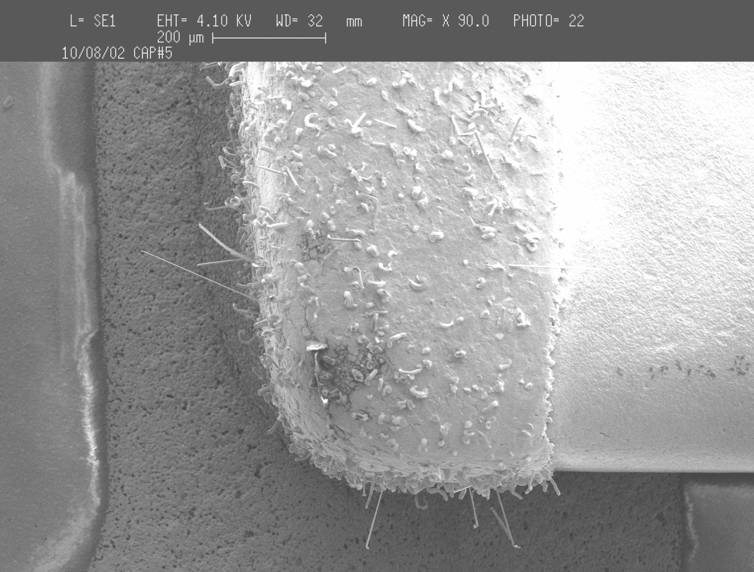
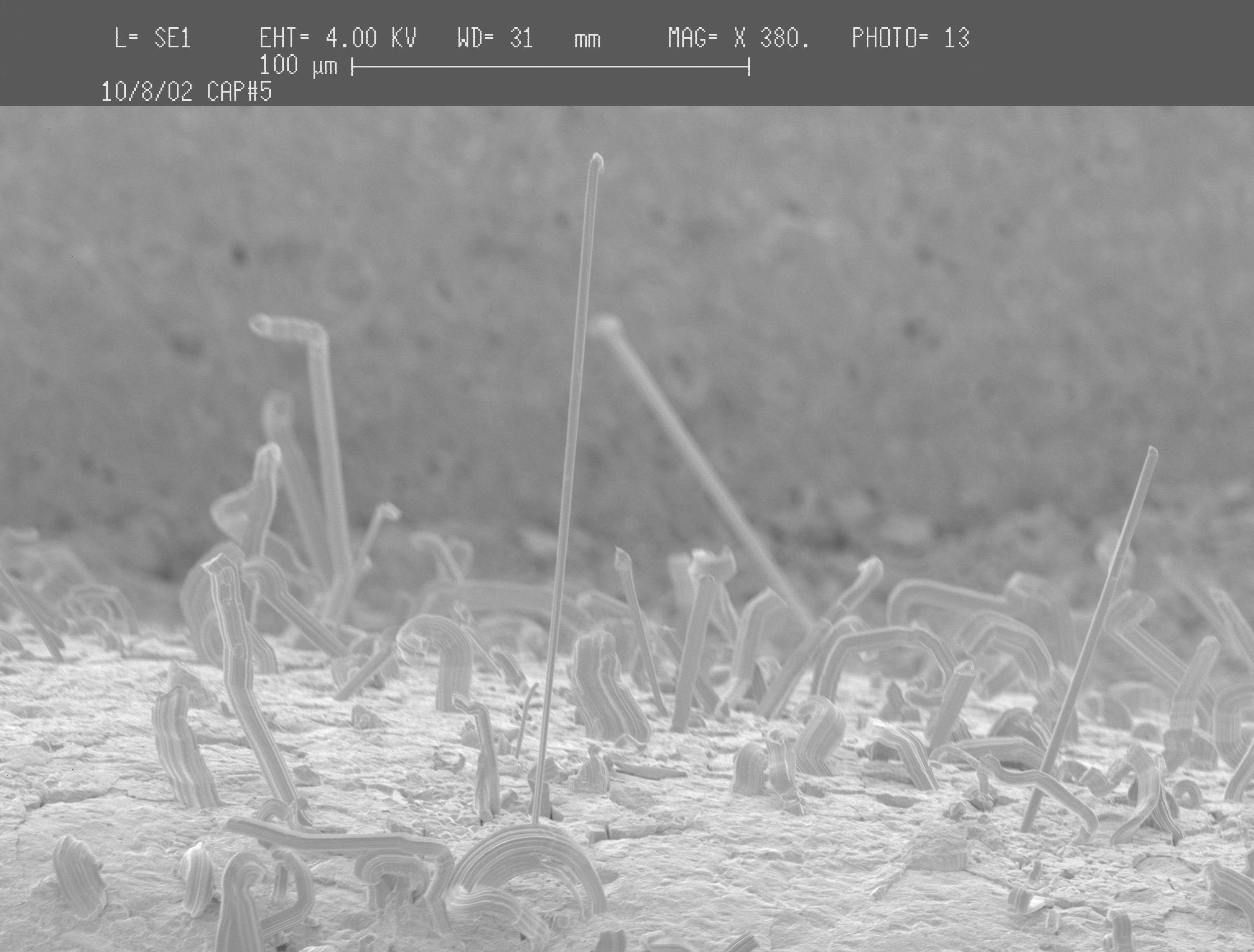
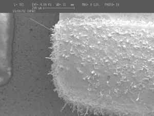
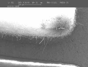
October 2002 - Photos Below are
from Same Capacitors T-cycled in early 2001 then stored in Ambient Office
Conditions
Courtesy NASA Goddard Space Flight Center Parts
Analysis Lab |
 |
 |
 |
 |
 |
 |
|
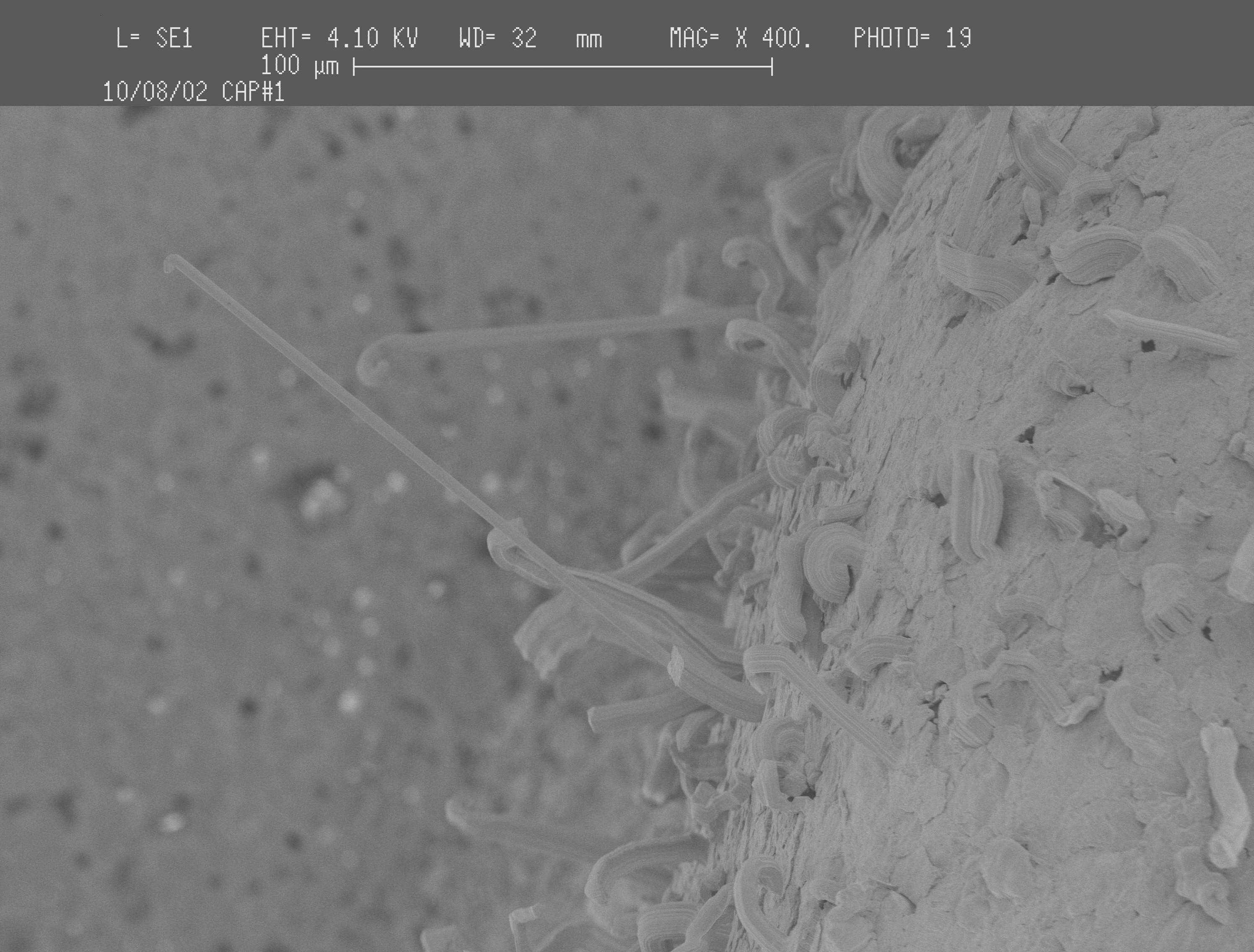
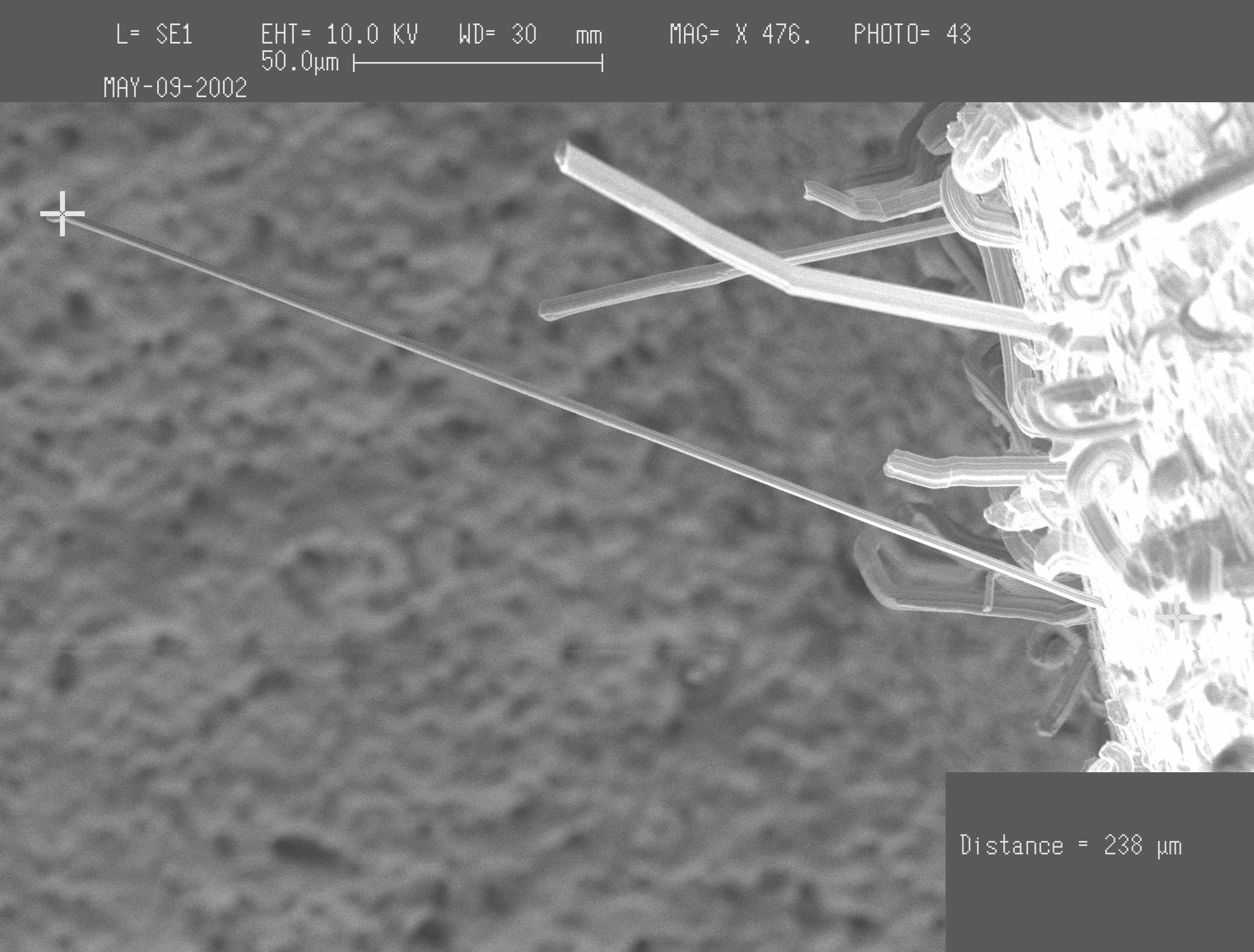
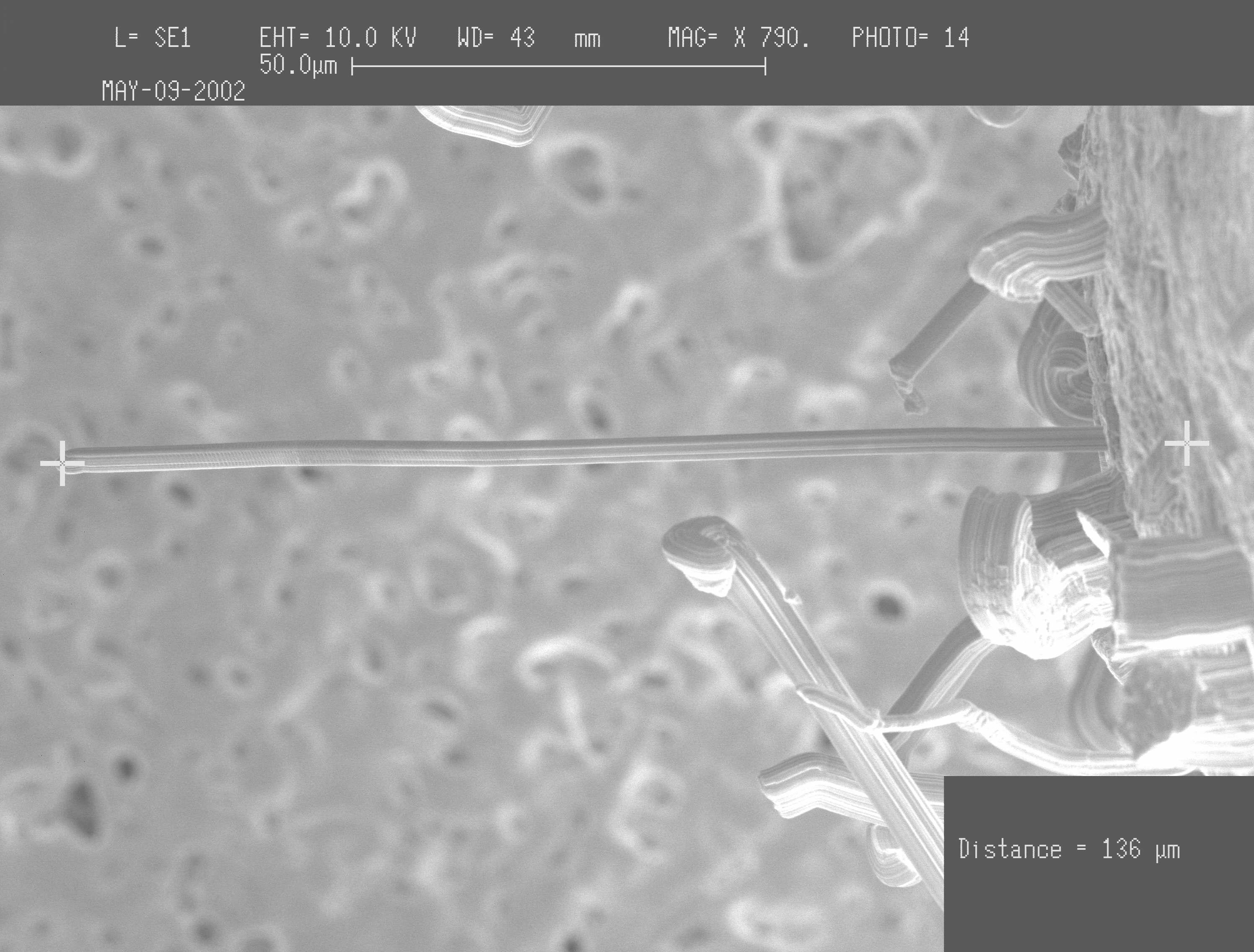
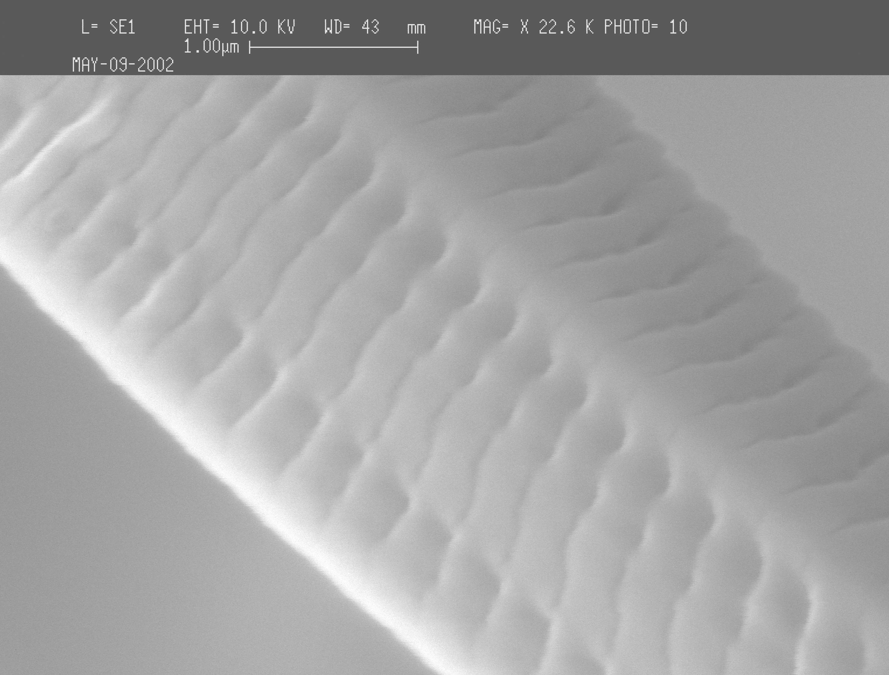
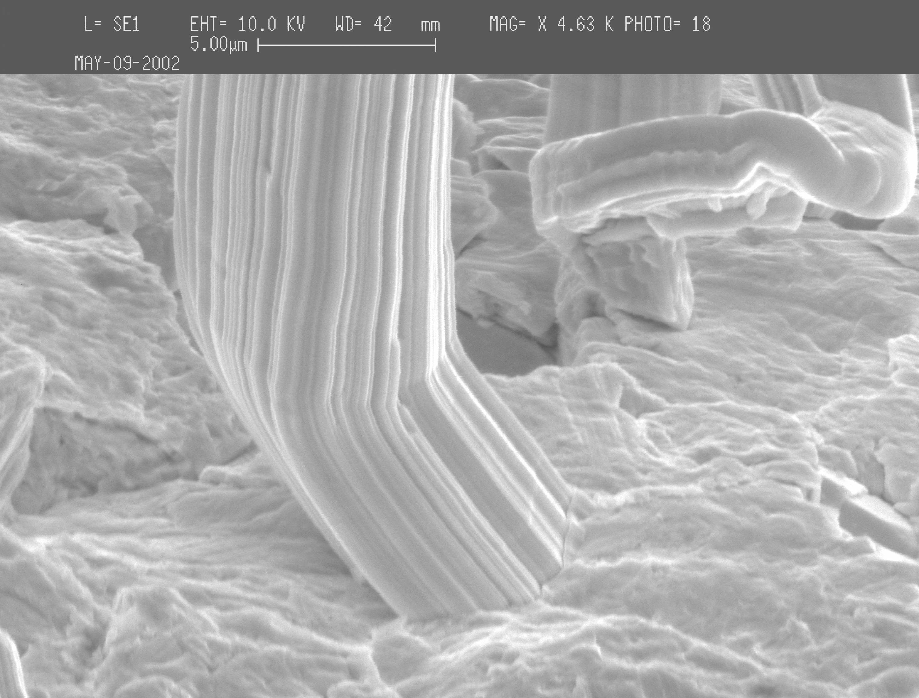
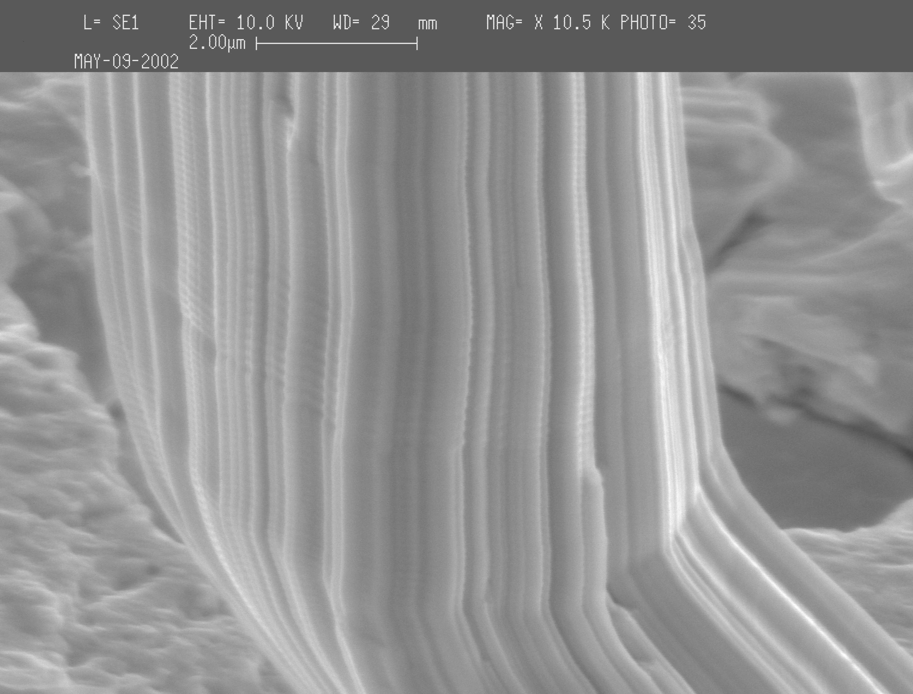
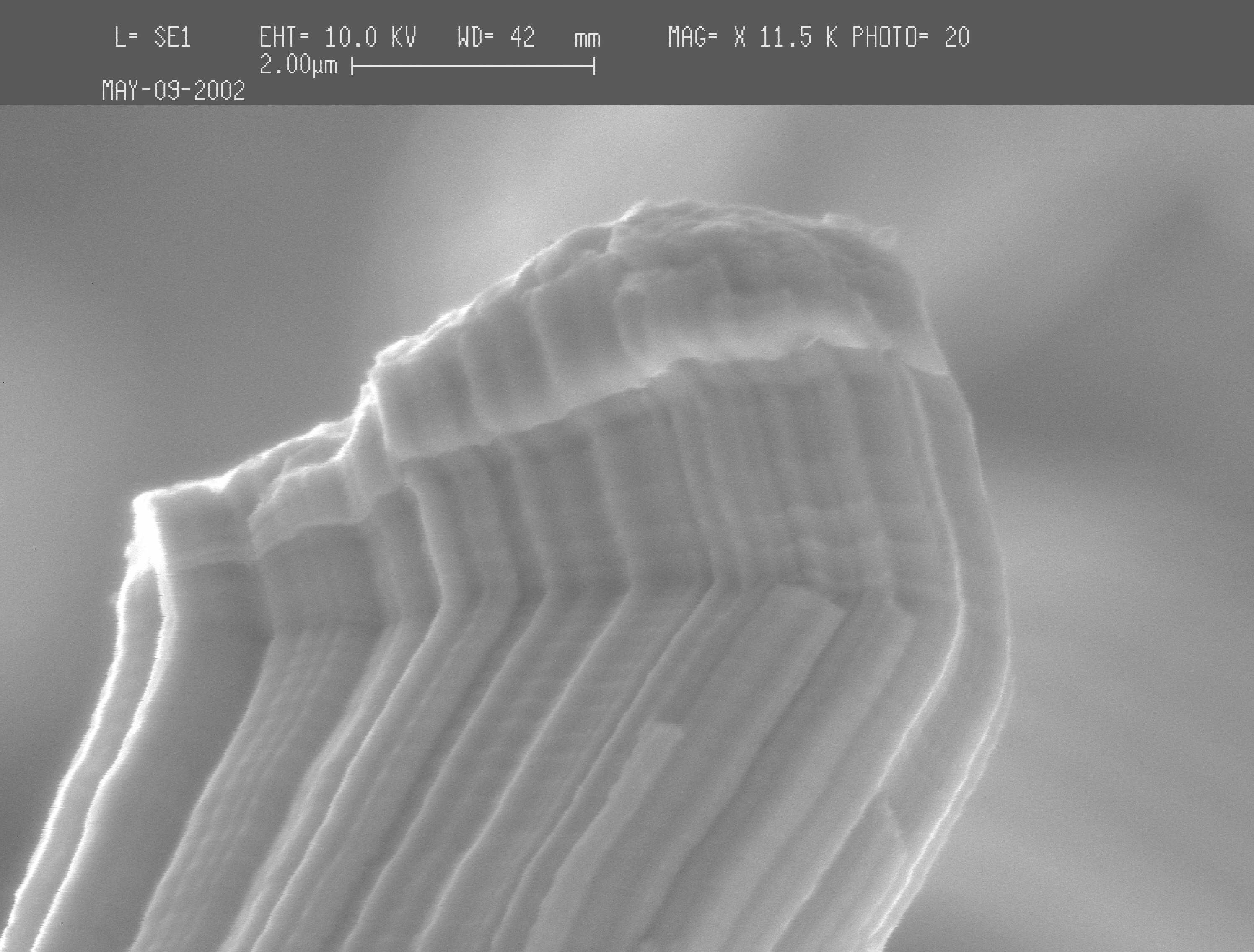
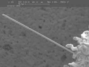
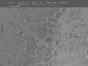
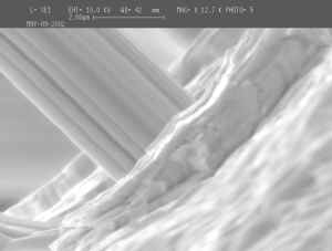
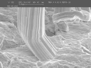
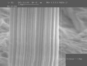
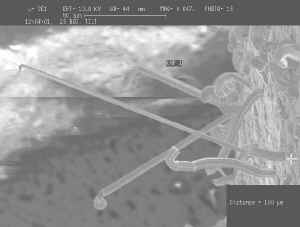
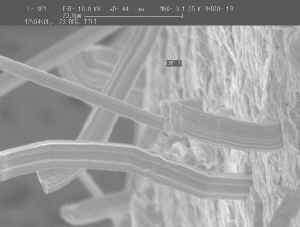
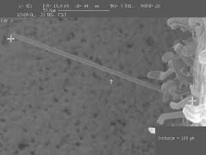
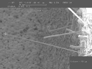
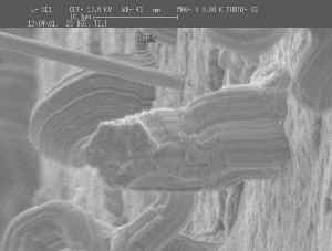
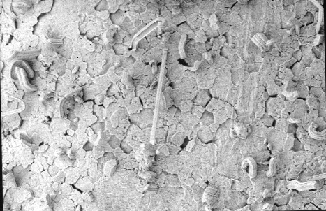
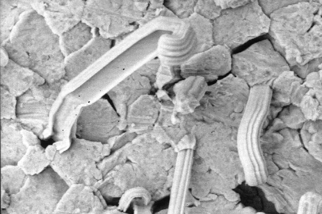
May 2002- High Power SEM Images
to Show How SOME of the Whiskers have Circumferential Rings
Courtesy of NASA Goddard Space Flight Center |
|
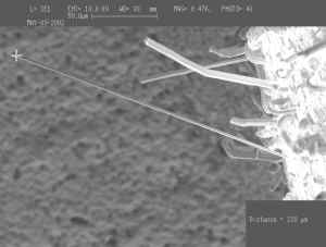
Longest Whisker Found ~ 240 microns
|

Whisker "#1" - Overall View |
Whisker
"#1" - Base of Whisker |
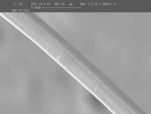
Whisker "#1" - Middle of Whisker (Notice
"Rings") |
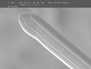
Whisker "#1" - Tip of Whisker (Notice
"Rings") |

Whisker "#1" - Close Up of
"Rings" |

Whisker "#2" - Overall View |
Whisker "#2" - Base of Whisker |

Whisker "#2" - Kink Near Base (Notice
"Rings") |

Whisker "#2" - Tip of Whisker (Notice
"Rings") |
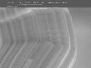
Whisker "#2" - Close Up of Tip (Notice
"Rings") |
Whisker "#2" - Middle of Whisker (Notice
"Rings") |
|
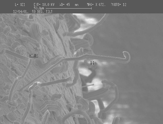
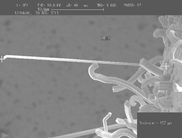
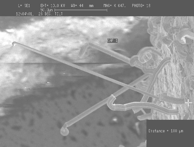
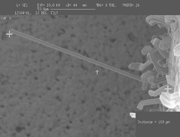
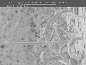
December
2001: ~ 6 to 8 Months of Ambient Storage Have Elapsed Since
the Thermal Cycle Exposure
| The sample hybrid (with chip caps still mounted) has
been stored at ambient condition ever since being received at GSFC. |
| SEM inspection in December 2001 shows that some of
the tin whiskers on the chip caps have grown substantially since the
previous inspection. A few whiskers are now greater than 200
microns long (some approaching 250 microns). Previous examination in
August 2001 showed maximum whisker length was approximately 100
microns. |
| Capacitors will be retained for additional ambient
storage and inspection |
|
 |
 |
 |
 |
 |
 |
 |
 |
 |
|
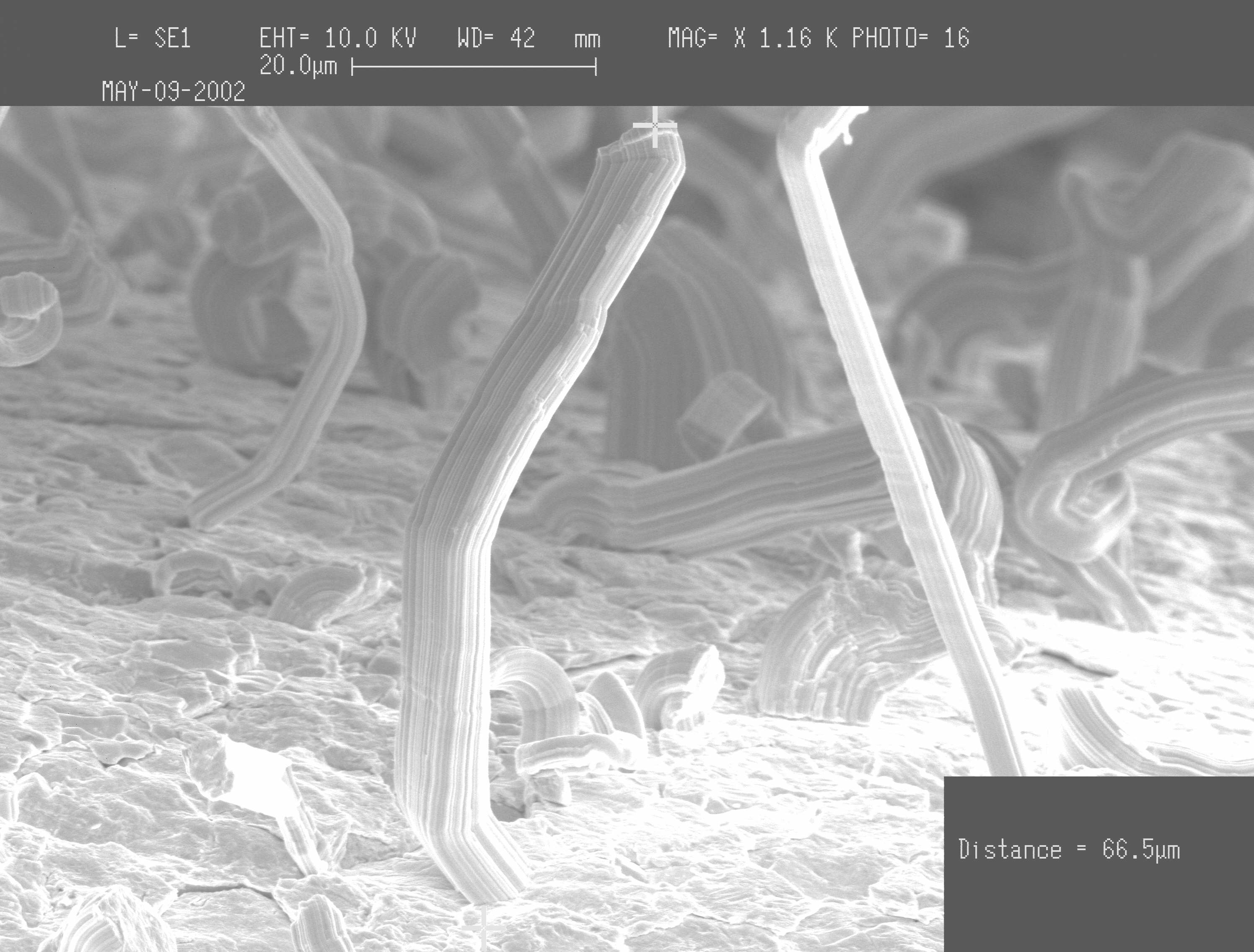
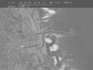
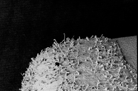
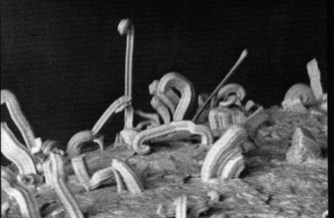
August 2001 -
NASA Goddard Inspection to Confirm Observations Reported by Hybrid
Manufacturer
Q1. What is the max length of whisker and
typical length of whisker? Quantify typical length of whiskers.
A1. The max length of whisker was estimated to be 100 um
and the typical length is estimated to be around 25um to 50 um.
This cap is populated with mainly two types of whiskers: toothpaste like
(thick curly type) and needle like. The density of the whiskers
(including both types) is estimated to be 800 whiskers/mm2 (conservative
estimate) which can be compared to GSFC experiment using pure tin plated
brass substrates with ~50 whiskers/mm2 (max density sample). Among
entire whisker population, 5% is needle like whiskers that would grow
potentially dangerously long.
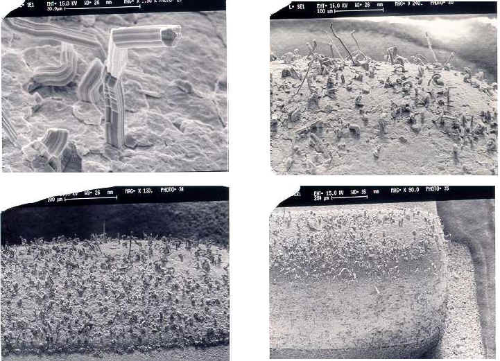
Photos Courtesy of NASA Goddard Space
Flight Center
Q2. EDAX on the cap termination to confirm if
there's any lead (Pb) content?
A2. EDAX results showed Sn element exclusively. No Pb
was observed (Accuracy: Elapsed time was 500 sec.).
Q3. Examine whisker growth at the
conductive epoxy interface, and WITHIN the conductive epoxy?
A3. The whiskers are present only on plated termination on
both sides of the caps. No whiskers were observable at the
conductive epoxy interface nor within the conductive epoxy.
Q4. Analyze the grain structure of the
plating (quantify grain size) if possible.
A4. This could not be done with SEM. Future Work will attempt
to analyze the grain structure using Oriented Imaging Microscope (OIM) for
grain structure analysis |
|
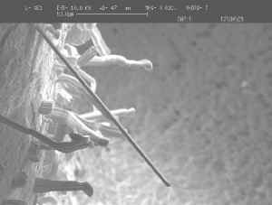
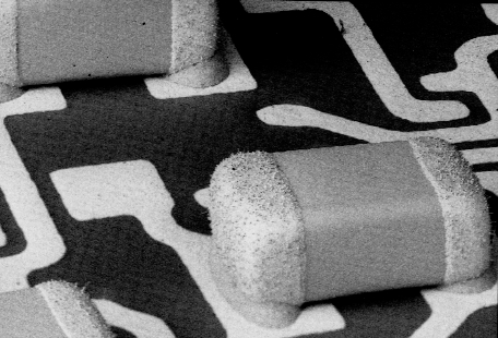
February 2001-Photos Below Were Taken Shortly
After 200+ Temp Cycles from -40°C to +90°C
Courtesy of I. Hernefjord |
 |
 |
 |
 |
 |
|
|
Previously
Published Research on MLCCs and Tin Whiskers:
Prior to 2002
published research has suggested that multilayer ceramic capacitors (MLCCs)
are "immune" to the risks of whisker formation. Research by Murata**
(M. Endo 1997) showed 18 years of whisker-free performance of pure tin
plated MLCCs when stored continuously at 50°C. In
summary, the rationale given for this protection included:
| Use of Nickel
barrier metallization under the tin electroplate |
| Use of
"Matte" tin plating chemistries and processes |
| Relatively
"large" (>5 um), well-polygonized tin grains |
| Post
electroplating annealing processes |
** M. Endo, S. Higuchi, Y. Tokuda, and Y. Sakabe, "Elimination of Whisker Growth on Tin Plated Electrodes", Proceedings of the 23rd International
Symposium for Testing and Failure Analysis, pp. 305 - 311, October 27-31,
1997
|