|
Basic Information
- What is Wire Bonding?
- Background./Brief History of Wire Bonding.
- How are they formed?
- What are the wire materials used?
- What are the types of wire bonds?
- What are the typical wire bond failures mechanisms?
- How are they evaluated?
What is Wire Bonding?
A method used to attach a fine wire, usually 1 to 3 mils in diameter, from one connection pad to another, completing the electrical connection in an electronic device, is called Wire Bonding. The pads can be bond sites on the semiconductor chip or metallized bond sites on interconnection substrates. Semiconductor die can also be wire bonded to metal lead frames as is done in plastic encapsulated devices. The methods presently used to wire bond include thermocompression, ultrasonic and thermosonic.
Background
According to recent literature, 4x 10^12 wires are bonded every year in the world and most are used in the approximately 40 to 50 billion integrated circuits (ICs) produced. Other types of bonding technology such C4 (Controlled Collapsed Chip Connection or Flip Chip) or TAB (Tape Automated Bonding) also have been used in parallel with conventional wire bonding technology. Wire bonding continues to be popular and dominant in the field of bonding technologies in the industry.
In the past, a large proportion of all semiconductor-device field failures were caused by wire bonds and the number of known failure mechanism were quite limited. Through the improvement of bonding technology the reliability of wire bonds is increasing, as is our understanding of the failure modes, though they continue to plague new manufacturing lines.
Brief History of Wire Bonding
- 1957 - Bell Labs was the first to publish information regarding wire bonding history of bonders
- 1959 - J.W. Beams reported his characterization of metallic thin film strength.
- 1971 - Nowaskowski & Villela found three variations of power cycling tests.
- 1972 - Horsting publishes “Purple Plague and Gold Purity,” describing contamination based void formation in intermetallic layers
- 1972 - Ravi & Philofsky: Machine for accelerated tests of various wires.
- 1973 - Ravi & Philofsky published a failure prediction model of thin films.
- 1973 - C.N. Adams developed a model for wire failure near ball bond.
- 1974 - G. Harman sited cause as manufacturing defects or environmental stresses.
- 1989 ~1991 - M. Pecht & A. Dasgupta models for wire flexture, pad & wire & substrate shear, and axial tension.
- 2000+ - Ramminger's work on under-wedge cracking.
How are They Formed?
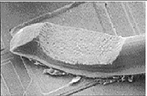
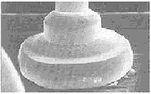
There are basically two forms of wire bonds. They are Wedge bonds and Ball bonds. Recent study shows that about 90% of all electronic packages and assemblies are produced using ball bonds and about 10% are produced with wedge bonds. An increase in the use of ball bonding is expected as semiconductor devices increase in functionality and decrease in size causing smaller bond pads and closer bond pad spacing.

Wedge Bond

Ball Bond
What are the Wire Materials?
The most widely used wire materials are Gold (Au) and Aluminum (Al) however, Silver (Ag) and Copper (Cu) are also used. Copper wire (ball bonding) has gained considerable attention due to its economic advantage and strong resistance to sweeping (leaning of the stress relief loop until it touches an adjacent bond wire). Bonding these wire materials to different pad materials creates different metallurgical systems called intermetallics. Gold was the original material used when wire bonding technology was developing. Aluminum has become popular due to its good electrical performance and lower cost. Gold wire can be bonded in the shape of a wedge or a ball. Ball bonds can be used in very tight spacing. Aluminum wire can only be wedge bonded and so is limited when spacing is tight.
What are the Main Methods for Wire Bonding ?
- Thermocompression (Wedge-Ball)
Thermocompression bonding was first presented by Bell Laboratories in 1957 and extensively used until Ultrasonic bonding technology showed up in the mid 1960s. Thermocompression bonding requires a high-force on a surface with a high temperature; around 300°C. It provides excellent, reliable Al-Au bonds with flexibility in the bonding direction allowed. The wire material is Au but the pad can be Au or Aluminum.
-Ultrasonic (Wedge-Wedge Bonding)
Ultrasonic bonding is the most common bonding technology used for Al bond wires and is performed at ambient temperature. Bonding is formed as a wedge bond by pressure and vibrational energy.
-Thermosonic (Ball-Wedge Bonding)
Thermosonic bonding is used for Au wires and currently comprises about 90% of all wire bonding. It is done at temperatures of around 100°C to 240°C. Bonding is formed when the ultrasonic energy combines with the capillary technique of thermocompression bonding. Occasionally, it is used for Au wedge-wedge bonding, but mostly it is best suited for a ball-wedge bond.
A comparison of three types of wire bonding technologies is shown in table below.
| Wirebonding |
Operating Temperature |
Wire Materials |
Pad Materials |
Note |
| Thermocompression |
300-500°C |
Au |
Al, Au |
High pressure, no ultrasonic energy |
| Ultrasonic |
25°C |
Au, Al |
Al, Au |
Low pressure in ultrasonic energy |
| Thermosonic |
100-240°C |
Au, Cu |
Al, Au |
Low pressure in ultrasonic energy |
What are the Typical Failure Mechanisms?
Common failures are:
- Cratering or peeling of a wire bond pad
- Wire bond fracture (leading to weak bonds or bond lifts)
- Inconsistent tails (which cause shorting with other bonds or traces on the surrounding circuitry)
- Poor welding (leading to weak bonds)
- Improper positioning on the bond pad (leading to shorts and bad welds)
How are They Evaluated?
Wire bonding evaluation criteria varies depending on the application requirements. Evaluation methods can be found in several published standards, but the most common standard is MIL-STD-883. It lists the following methods:
Note: Selection of the test method may vary depending on mission requirement.
|


