|
|
|
|
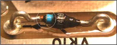
Damage from Incorrect Lead Forming |
|
6. Components: Improper lead forming resulting in part damage
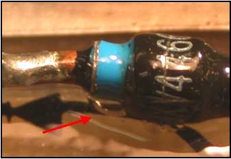
Failure of this glass bodied diode was attributed to a crack induced by stresses imposed during the lead forming process. The operator did not support the part lead on the body side of the lead during the forming process. Also the bend in the lead should have been further from the part body a (minimum of 2 lead diameters) before the first bend.
Reference :
NASA-STD-8739.3 Parts Mounting, 8.1 General
6. Lead Bending and Cutting.
a. During bending or cutting, part leads shall be supported on the body side to minimize axial stress and avoid damage to seals or internal bonds. The distance from the bend to the end seal shall be approximately equal at each end of the part. The minimum distance from the part body or seal to the start of the bend in a part lead shall be 2 lead diameters for round leads and 0.5mm (0.020 inch) for ribbon leads. The stress relief bend radius shall not be less than the lead diameter or ribbon thickness. The direction of the bend should not cause the identification markings on the mounted part to be obscured. Where the lead is welded (as on a tantalum capacitor) the minimum distance is measured from the weld.
|
|
|
|
|